|
|
| PJRC.COM Offline Archive, February 07, 2004 Visit this page on the live site |
| ||
|
Shopping Cart
|
| Home | MP3 Player | 8051 Tools | All Projects | PJRC Store | Site Map |
|
You are here:
MP3 Player
| Search PJRC |
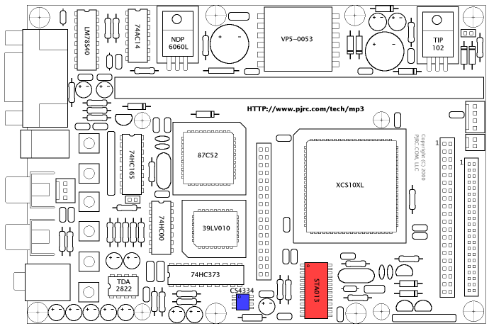
| Quantity | Color | Components |
|---|---|---|
| 1 | . | STA013 MP3 Decoder IC, 32 pin SOP Package |
| 1 | . | CS4334 24 Bit Digital to Analog Converter IC |
| 1 | not shown | MAX810-3.0, SOT-23 Package |