<- previous index next ->
Given that you can get a 3D scene rendered, you may want:
a) to have the user move the scene or
b) have the user move (the location of the users eye).
The minor difference is that moving the scene left gives the
eye the impression that the scene is moving to the left.
Whereas, moving the direction the eye is looking to the left
gives the brain the impression the scene is moving to the right.
Be careful of the plus or minus sign on rotation matrices.
Modeling and Simulation
There are six degrees of freedom of motion and the problem
for the GUI programmer is how to make it convenient and intuitive
for the user. My example code using the keyboard for x,y,z r,p,h
in pilot.c is very hard to use and
does not represent the controls in an airplane.
 Remember! All free objects rotate about their center of gravity.
The Longitudinal, Lateral and Vertical axes all pass through
the center of gravity. Position, Velocity and Acceleration are
applied to the center of gravity. The rendering then draws
relative to the six degrees of freedom about the center of
gravity.
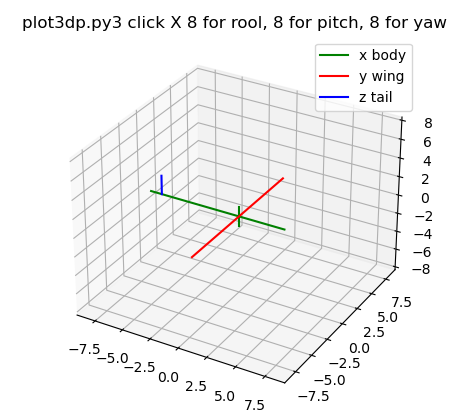
Incomplete aircraft, step by step 8 rool, 8 pitch, 8 yaw.
Requires 24 clicks to see all.
test_rotate.py3 test source code
test_rotate_py3.out
plot3dp.py3 source code
Remember! All free objects rotate about their center of gravity.
The Longitudinal, Lateral and Vertical axes all pass through
the center of gravity. Position, Velocity and Acceleration are
applied to the center of gravity. The rendering then draws
relative to the six degrees of freedom about the center of
gravity.
Incomplete aircraft, step by step 8 rool, 8 pitch, 8 yaw.
Requires 24 clicks to see all.
test_rotate.py3 test source code
test_rotate_py3.out
plot3dp.py3 source code
 Russian Fighter, manuvers
FYI. A typical small airplane has a yoke with what looks like a steering
wheel that can also move forward and backward. The foot pedals
move in opposite directions, right down causes left up. This only provides
control of three (3) degrees of freedom, yet is sufficient for the
pilot to fly the airplane. Turning the wheel causes roll (ailerons move),
pushing the wheel causes pitch (elevators move) and pushing the
petals causes yaw (rudder moves). The airplane is turned
by causing roll with small compensating pitch to maintain constant
altitude (changes x,y). Performed properly, this is called a coordinated
turn. The radius of the turn may be defined as "g" force, the equivalent
force of gravity pushing the pilots down into their seats.
The airplane changes altitude using the pitch control
(changes z). Of course the airplane must be moving to stay in the air,
thus some velocity vector in x,y,z determines the direction of motion.
The typical way to model the flight of an airplane is to consider
the airplane to be at position x,y,z at some time "t". The airplane
has some velocity vector vx,vy,vz and the pilots three controls
in conjunction with the airplanes aerodynamics determine the
acceleration vector ax,ay,az. Then at some delta time later "t+dt"
the position is updated x,y,x = x,y,z + dt * vx,vy,vx and
velocity is updated vx,vy,vz = vx,vy,vz + dt * ax,ay,az .
Similar updates are computer for the angles roll, pitch and
yaw (not really heading). Angular velocities are vr,vp,vy and
angular accelerations ar,ap,ay are computed based on the
pilots three controls in conjunction with the airplanes aerodynamics.
Then at some delta time later "t+dt" the roll, pitch, yaw angles
are updated r,p,y = r,p,y + dt * vr,vp,vy and
angular velocities are updated vr,vp,vy = vr,vp,vy + dt * ar,ap,ay .
The basis of motion is from calculus:
velocity(time T) = velocity(time 0)
+ integral from 0 to T acceleration(t) dt
position(time T) = position(time 0)
+ integral from 0 to T velocity(t) dt
The discrete numerical calculation approximates the analytic expression
using small discrete time steps, dt, and simple multiplication and addition.
There is, of course, a fourth control: the throttle and the brakes that
are primarily used for takeoff and landing. This control contributes
to the acceleration along the longitudinal axis of the airplane.
Technically, the positions, velocities and accelerations are all
computed at the center of gravity of the airplane. The longitudinal,
lateral and vertical axes pass through the airplanes center of
gravity. For graphic rendering, particularly at takeoff and landing,
compensation must be made for height of the center of gravity above
the ground.
OK, so how are the accelerations computed?
It boils down to Sir Isaac Newton, F = m a .
Force equals mass times acceleration. Given that we know the weight
of the airplane, we can compute the airplanes mass, m.
Then, from the throttle position, we can fit a low degree polynomial
to give the force (called thrust) as a function of throttle position
and velocity. Thus, we compute the acceleration along the longitudinal
axis from a = F/m and resolve the force into ax,ay,az.
Multiple forces add and thus multiple accelerations add.
The force in the direction opposite thrust is called drag. Drag is
computed based on the coefficient of drag, Cd, that is a function
of the physical shape of the airplane, multiplied by air density,
surface area of the airplane, and velocity squared over 2. The force
along the vertical axis, in the up direction is called lift. Lift is
computed based on coefficient of lift, Cl, that is a function of the
physical shape of the airplane, multiplied by air density, surface
area of the airplane times velocity squared then divided by 2.
D = Cd * r * Area * V^2 / 2 where r depends on air density and units
L = Cl * r * Area * V^2 / 2 e.g. r = 0.00237 slugs/cu ft
The roll, pitch and yaw angular acceleration are typically modeled
by low degree polynomials on the respective control position, multiplied
by velocity squared (For small aircraft well below Mach 1.0).
Thus, there are many, relatively simple, steps to compute the
aircraft's 3D position verses time and render the aircraft's motion.
Additional GUI user control may be desired to allow for the pilot
to look left and right, up and down. This addition becomes a user
interface problem on most standard computers.
One possible user interface is a "wheel mouse". The left-right
mouse motion is interpreted as roll left-right. The forward-back
mouse motion is interpreted as pitch down-up. The center wheel
motion forward-back is interpreted as rudder position left-right.
Throttle and brakes must be input from the keyboard. Anyone who
has flown a small aircraft or a radio control aircraft understands
the awkwardness of the computer GUI. The radio control interface
is two joy sticks (left thumb and right thumb) controlling
rudder-throttle and roll-pitch.
A little hard to read, for a specific wing shape, the chart shows
Cl and Cd as a function of angle of attack. The angle of attack is
the angle between the chord of the wing and the velocity vector.
Russian Fighter, manuvers
FYI. A typical small airplane has a yoke with what looks like a steering
wheel that can also move forward and backward. The foot pedals
move in opposite directions, right down causes left up. This only provides
control of three (3) degrees of freedom, yet is sufficient for the
pilot to fly the airplane. Turning the wheel causes roll (ailerons move),
pushing the wheel causes pitch (elevators move) and pushing the
petals causes yaw (rudder moves). The airplane is turned
by causing roll with small compensating pitch to maintain constant
altitude (changes x,y). Performed properly, this is called a coordinated
turn. The radius of the turn may be defined as "g" force, the equivalent
force of gravity pushing the pilots down into their seats.
The airplane changes altitude using the pitch control
(changes z). Of course the airplane must be moving to stay in the air,
thus some velocity vector in x,y,z determines the direction of motion.
The typical way to model the flight of an airplane is to consider
the airplane to be at position x,y,z at some time "t". The airplane
has some velocity vector vx,vy,vz and the pilots three controls
in conjunction with the airplanes aerodynamics determine the
acceleration vector ax,ay,az. Then at some delta time later "t+dt"
the position is updated x,y,x = x,y,z + dt * vx,vy,vx and
velocity is updated vx,vy,vz = vx,vy,vz + dt * ax,ay,az .
Similar updates are computer for the angles roll, pitch and
yaw (not really heading). Angular velocities are vr,vp,vy and
angular accelerations ar,ap,ay are computed based on the
pilots three controls in conjunction with the airplanes aerodynamics.
Then at some delta time later "t+dt" the roll, pitch, yaw angles
are updated r,p,y = r,p,y + dt * vr,vp,vy and
angular velocities are updated vr,vp,vy = vr,vp,vy + dt * ar,ap,ay .
The basis of motion is from calculus:
velocity(time T) = velocity(time 0)
+ integral from 0 to T acceleration(t) dt
position(time T) = position(time 0)
+ integral from 0 to T velocity(t) dt
The discrete numerical calculation approximates the analytic expression
using small discrete time steps, dt, and simple multiplication and addition.
There is, of course, a fourth control: the throttle and the brakes that
are primarily used for takeoff and landing. This control contributes
to the acceleration along the longitudinal axis of the airplane.
Technically, the positions, velocities and accelerations are all
computed at the center of gravity of the airplane. The longitudinal,
lateral and vertical axes pass through the airplanes center of
gravity. For graphic rendering, particularly at takeoff and landing,
compensation must be made for height of the center of gravity above
the ground.
OK, so how are the accelerations computed?
It boils down to Sir Isaac Newton, F = m a .
Force equals mass times acceleration. Given that we know the weight
of the airplane, we can compute the airplanes mass, m.
Then, from the throttle position, we can fit a low degree polynomial
to give the force (called thrust) as a function of throttle position
and velocity. Thus, we compute the acceleration along the longitudinal
axis from a = F/m and resolve the force into ax,ay,az.
Multiple forces add and thus multiple accelerations add.
The force in the direction opposite thrust is called drag. Drag is
computed based on the coefficient of drag, Cd, that is a function
of the physical shape of the airplane, multiplied by air density,
surface area of the airplane, and velocity squared over 2. The force
along the vertical axis, in the up direction is called lift. Lift is
computed based on coefficient of lift, Cl, that is a function of the
physical shape of the airplane, multiplied by air density, surface
area of the airplane times velocity squared then divided by 2.
D = Cd * r * Area * V^2 / 2 where r depends on air density and units
L = Cl * r * Area * V^2 / 2 e.g. r = 0.00237 slugs/cu ft
The roll, pitch and yaw angular acceleration are typically modeled
by low degree polynomials on the respective control position, multiplied
by velocity squared (For small aircraft well below Mach 1.0).
Thus, there are many, relatively simple, steps to compute the
aircraft's 3D position verses time and render the aircraft's motion.
Additional GUI user control may be desired to allow for the pilot
to look left and right, up and down. This addition becomes a user
interface problem on most standard computers.
One possible user interface is a "wheel mouse". The left-right
mouse motion is interpreted as roll left-right. The forward-back
mouse motion is interpreted as pitch down-up. The center wheel
motion forward-back is interpreted as rudder position left-right.
Throttle and brakes must be input from the keyboard. Anyone who
has flown a small aircraft or a radio control aircraft understands
the awkwardness of the computer GUI. The radio control interface
is two joy sticks (left thumb and right thumb) controlling
rudder-throttle and roll-pitch.
A little hard to read, for a specific wing shape, the chart shows
Cl and Cd as a function of angle of attack. The angle of attack is
the angle between the chord of the wing and the velocity vector.
 Lift equations
Local copies at
NACA-460 1933 78 airfoils and
NACA-824 1945 Airfoil Summary
The reference material comes from NACA the predecessor of NASA.
NACA-460 1933 78 airfoils and
NACA-824 1945 Airfoil Summary and
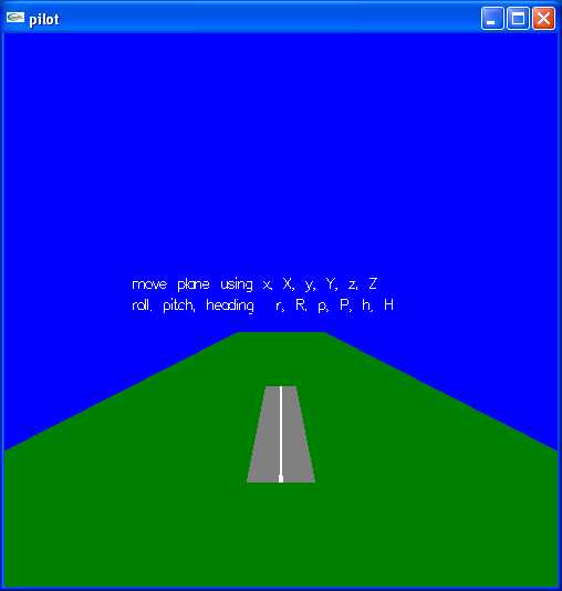
A crude airplane can be generated and manually moved,
the usual x, y, z, roll, pitch, heading:
Lift equations
Local copies at
NACA-460 1933 78 airfoils and
NACA-824 1945 Airfoil Summary
The reference material comes from NACA the predecessor of NASA.
NACA-460 1933 78 airfoils and
NACA-824 1945 Airfoil Summary and
A crude airplane can be generated and manually moved,
the usual x, y, z, roll, pitch, heading:
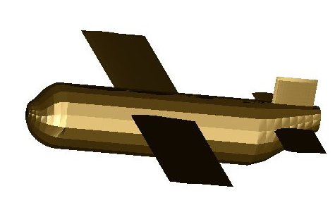 This could be modified to be "flown" using a script
or the user moving the mouse. A background could be
added and coloring and decorations added to the plane.
plane2gl.c
plane_fuse.h
This could be modified to be "flown" using a script
or the user moving the mouse. A background could be
added and coloring and decorations added to the plane.
plane2gl.c
plane_fuse.h
Accurate Modeling and Simulation
Of course, this is not the end of the complexity of accurate modeling
and simulation. When a person moves a control, that signal typically
goes to a servo, which sends signals to the actuator to move the
physical object the person wants to control. A servo works on the
principal of measuring where the physical object is, x, how the
physical object is moving, vx, and the persons desired position xp.
There is some time lag as the servo drives the physical object
to make x equal to xp. This is known as a servo loop or control loop.
In general, human factors requires that the person be provided a
control for position or angle rather that acceleration. Embedded
computers or electro-mechanical devices cause the persons control
signal to be translated to a force that in turn causes acceleration
that ultimately causes the physical device to reach the commanded
position.
Many planes to model:
Top 10
HW4 is assigned, display fonts.
<- previous index next ->
Many web sites on Java GUI, AWT, Swing, etc.
Many web sites on Python wx, tk, qt, etc.