<- previous index next ->
Combinational digital logic uses Boolean Algebra.
The basic relations are well known, yet several notations
are used.
When using binary arithmetic on binary numbers and using
the least significant bit of the result:
Notation A: use words "and" "or" "not" etc.
Notation B: use characters & for "and", | for "or", ~ for "not"
Notation C: use characters * for "and", + for "or", - for "not"
Notation D: use symbols "dot" for "and", + for "or", bar for "not"
Notation E: use symbols "blank" for "and", + for "or", bar for "not"
Generally, the symbols for "and" are like the symbols for multiply,
the symbols for "or" are like the symbols for addition.
In mathematics, multiplication always has precedence over addition,
do not expect "and" to always have precedence over "or.
Here are 19 basic identities that can be used to simplify
or convert one Boolean equation to another.
1. X + 0 = X "or" anything with zero gives anything
2. X * 1 = X "and" anything with one gives anything
3. X + 1 = 1 "or" anything with one gives one
4. X * 0 = 0 "and" anything with zero gives zero
5. X + X = X "or" with self gives self
6. X * X = X "and" with self gives self
_
7. X + X = 1 "or" with complement gives one
_
8. X * X = 0 "and" with complement gives zero
9. not(not(X)) = X any even number of complements cancel
10. X + Y = Y + X "or" is commutative
11. X * Y = Y * X "and" is commutative
12. X + (Y + Z) = (X + Y) + Z "or" is associative
13. X * (Y * Z) = (X * Y) * Z "and" is associative
14. X * (Y + Z) = X * Y + X * Z distributive law
15. X + Y * Z = (X + Y) * (X + Z) distributive law
_________
_ _
16. X + Y = ( X * Y ) DeMorgan's theorem
_________ _ _
17. ( X + Y ) = X * Y DeMorgan's theorem
_________ _ _
18. ( X * Y ) = X + Y DeMorgan's theorem
_________
_ _
19. X * Y = ( X + Y ) DeMorgan's theorem
Basically, DeMorgan's theorem says:
Convert "and" to "or", negate the variables and negate the entire expression.
Convert "or" to "and", negate the variables and negate the entire expression.
Any truth table can be converted to a equation or schematic.
Given any truth table, there is a simple procedure for generating
a Boolean equation that uses "and", "or" and "not" (any representation).
First an example:
Given truth table
a b | c for each row where 'c' is 1, _
----+-- create an "and" with 'a' if 'a' is 1, or 'a' if 'a' is 0
0 0 | 1 _
0 1 | 0 with 'b' if 'b' is 1, or 'b' if 'b' is 0
1 0 | 1 _ _
1 1 | 1 thus, first row a * b
_
third row a * b
fourth row a * b
now, "or" the "and's" to form the final equation
_ _ _
c = (a * b) + (a * b) + (a * b)
c <= (not a and not b) or (a and not b) or (a and b);
The schematic can be drawn directly,
one "and" gate for each row where 'c' is 1
with a bubble for each variable that is 0
 The general process to convert a truth table (or partial truth table)
to a Boolean equation using "and" "or" "not" is:
For each output
For each row where the output is 1
create a minterm that is the "and" of the input variables with
the input variable complemented when the input variable is 0.
The output is the "or" of the above minterms.
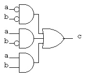
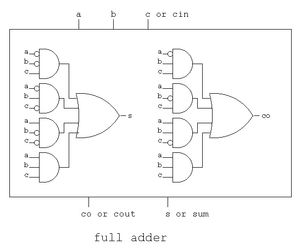
Another example with three input variables and two outputs.
a b c | s co
------+-----
0 0 0 | 0 0 _ _ _ _ _ _
0 0 1 | 1 0 s = (a*b*c) + (a*b*c) + (a*b*c) + (a*b*c)
0 1 0 | 1 0
0 1 1 | 0 1 _ _ _
1 0 0 | 1 0 co = (a*b*c) + (a*b*c) + (a*b*c) + (a*b*c)
1 0 1 | 0 1
1 1 0 | 0 1
1 1 1 | 1 1
(Note 4 outputs '1' in truth table, 4 and expressions ored)
The exact same information is presented by the schematic:
(Note 4 outputs '1' in truth table, 4 and gates feed 1 or gate)
The general process to convert a truth table (or partial truth table)
to a Boolean equation using "and" "or" "not" is:
For each output
For each row where the output is 1
create a minterm that is the "and" of the input variables with
the input variable complemented when the input variable is 0.
The output is the "or" of the above minterms.
Another example with three input variables and two outputs.
a b c | s co
------+-----
0 0 0 | 0 0 _ _ _ _ _ _
0 0 1 | 1 0 s = (a*b*c) + (a*b*c) + (a*b*c) + (a*b*c)
0 1 0 | 1 0
0 1 1 | 0 1 _ _ _
1 0 0 | 1 0 co = (a*b*c) + (a*b*c) + (a*b*c) + (a*b*c)
1 0 1 | 0 1
1 1 0 | 0 1
1 1 1 | 1 1
(Note 4 outputs '1' in truth table, 4 and expressions ored)
The exact same information is presented by the schematic:
(Note 4 outputs '1' in truth table, 4 and gates feed 1 or gate)
 Note that this is not a minimum representation, we will talk
about minimizing digital logic in a few lectures.
Note that this is not a minimum representation, we will talk
about minimizing digital logic in a few lectures.
Any equation can be converted to a truth table.
Example, convert c <= (a and b) or (not a and b);
_
c = (a * b) + (a * b) to a truth table
We can immediately construct the truth table structure.
We see the input variables are 'a' and 'b' and the output is 'c'
We generate all possible values for input by counting in binary.
a b | c
----+--
0 0 |
0 1 |
1 0 |
1 1 |
The only step that remains is to fill in the 'c' column.
For the first row, substitute 0 for 'a' and 0 for 'b' in the
equation and evaluate to find 'c'
_
c = (0 * 0) + (0 * 0) = (0) + ( 1 * 0) = 0 (using identities above)
For the second row, substitute 0 for 'a' and 1 for 'b' in the
equation and evaluate to find 'c'
_
c = (0 * 1) + (0 * 1) = (0) + ( 1 * 1) = 1 (using identities above)
For the third row, substitute 1 for 'a' and 0 for 'b' in the
equation and evaluate to find 'c'
_
c = (1 * 0) + (1 * 0) = (0) + ( 0 * 0) = 0 (using identities above)
For the fourth row, substitute 1 for 'a' and 1 for 'b' in the
equation and evaluate to find 'c'
_
c = (1 * 1) + (1 * 1) = (1) + ( 0 * 1) = 1 (using identities above)
Filling in the values for 'c' gives the completed truth table:
a b | c
----+--
0 0 | 0
0 1 | 1
1 0 | 0
1 1 | 1
Any digital logic schematic can be converted to a truth table.
Any equation can be converted to a schematic and any schematic
can be converted to an equation. When converting a schematic to
a truth table directly, you are simulating the actual behavior
of the digital logic.
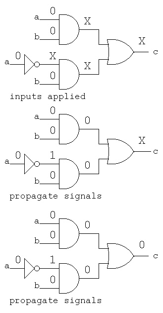
From schematic below we can immediately construct the truth table structure.
We see the input variables are 'a' and 'b' and the output is 'c'
We generate all possible values for input by counting in binary.
a b | c
----+--
0 0 |
0 1 |
1 0 |
1 1 |
Now, start by placing the values of input signals on the
input wires. a=0, b=0.
Note that signals other than inputs are labeled X for unknown.
Then, as shown on the sequence of figures, propagate the signals.
For each gate, use the gate input to compute the gate output.
This is actually how the hardware works. Each gate is continually
using the inputs to produce the output, with a small delay.
All gates operate in parallel. All gates operate all the time.
 Working a little faster, apply truth table inputs
a=0, b=1, then a=1, b=0, and finally a=1, b=1.
Working a little faster, apply truth table inputs
a=0, b=1, then a=1, b=0, and finally a=1, b=1.
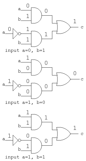 Filling in the values for 'c' gives the completed truth table:
a b | c
----+--
0 0 | 0
0 1 | 1
1 0 | 0
1 1 | 1
The previous lecture shows generating truth tables
with VHDL or Verilog logic simulators.
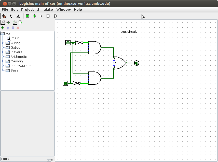
Diagrams made with logisim can have inputs set to 0 or 1
then simulate and see values of outputs:
Filling in the values for 'c' gives the completed truth table:
a b | c
----+--
0 0 | 0
0 1 | 1
1 0 | 0
1 1 | 1
The previous lecture shows generating truth tables
with VHDL or Verilog logic simulators.
Diagrams made with logisim can have inputs set to 0 or 1
then simulate and see values of outputs:
<- previous index next ->