<- previous index next ->
For these notes:
1 = true = high = value of a digital signal on a wire
0 = false = low = value of a digital signal on a wire
X = unknown or indeterminant to people, not on a wire
A digital logic gate can be represented at least three ways,
we will interchangeably use: schematic symbol, truth table or equation.
The equations may be from languages such as mathematics, VHDL or Verilog.
Digital logic gates are connected by wires. A wire or a group of
wires can be given a name, called a signal name. From an electronic
view the digital logic wire has a high or a low (voltage) but we
will always consider the wire to have a one (1) or a zero (0).
The basic logic gates are shown below.
The basic "and" gate:
truth table equation symbol  a b | c
----+-- c <= a and b;
0 0 | 0
0 1 | 0 c = a & b;
1 0 | 0
1 1 | 1 c = and(a,b)
Easy way to remember: The output is 1 when all inputs are 1, 0 otherwise.
In theory, an "and" gate can have any number of inputs.
a b | c
----+-- c <= a and b;
0 0 | 0
0 1 | 0 c = a & b;
1 0 | 0
1 1 | 1 c = and(a,b)
Easy way to remember: The output is 1 when all inputs are 1, 0 otherwise.
In theory, an "and" gate can have any number of inputs.
The basic "and" gate:
truth table equation symbol 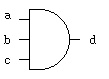 a b c | d d = and(a, b, c)
------+--
0 0 0 | 0 notice how a truth table has the inputs
0 0 1 | 0 counting 0, 1, 2, ... in binary.
0 1 0 | 0
0 1 1 | 0 the output (may be more than one bit) is
1 0 0 | 0 after the vertical line, on the right.
1 0 1 | 0
1 1 0 | 0
1 1 1 | 1
a b c | d d = and(a, b, c)
------+--
0 0 0 | 0 notice how a truth table has the inputs
0 0 1 | 0 counting 0, 1, 2, ... in binary.
0 1 0 | 0
0 1 1 | 0 the output (may be more than one bit) is
1 0 0 | 0 after the vertical line, on the right.
1 0 1 | 0
1 1 0 | 0
1 1 1 | 1
The basic "or" gate:
truth table equation symbol  a b | c
----+-- c <= a or b;
0 0 | 0
0 1 | 1 c = a | b;
1 0 | 1
1 1 | 1 c = or(a,b)
Easy way to remember: The output is 0 when all inputs are 0, 1 otherwise.
In theory, an "or" gate can have any number of inputs.
a b | c
----+-- c <= a or b;
0 0 | 0
0 1 | 1 c = a | b;
1 0 | 1
1 1 | 1 c = or(a,b)
Easy way to remember: The output is 0 when all inputs are 0, 1 otherwise.
In theory, an "or" gate can have any number of inputs.
The basic "or" gate:
truth table equation symbol 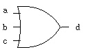 a b c | d d = or(a, b, c)
------+--
0 0 0 | 0 notice how a truth table has the inputs
0 0 1 | 1 counting 0, 1, 2, ... in binary.
0 1 0 | 1
0 1 1 | 1 the output (may be more than one bit) is
1 0 0 | 1 after the vertical line, on the right.
1 0 1 | 1
1 1 0 | 1
1 1 1 | 1
a b c | d d = or(a, b, c)
------+--
0 0 0 | 0 notice how a truth table has the inputs
0 0 1 | 1 counting 0, 1, 2, ... in binary.
0 1 0 | 1
0 1 1 | 1 the output (may be more than one bit) is
1 0 0 | 1 after the vertical line, on the right.
1 0 1 | 1
1 1 0 | 1
1 1 1 | 1
The basic "nand" gate:
truth table equation symbol 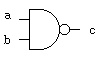 a b | c
----+-- c <= a nand b;
0 0 | 1
0 1 | 1 c = ~ (a & b);
1 0 | 1
1 1 | 0 c = nand(a,b)
Easy way to remember: "nand" reads "not and", the complement of "and".
a b | c
----+-- c <= a nand b;
0 0 | 1
0 1 | 1 c = ~ (a & b);
1 0 | 1
1 1 | 0 c = nand(a,b)
Easy way to remember: "nand" reads "not and", the complement of "and".
The basic "nor" gate:
truth table equation symbol 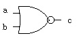 a b | c
----+-- c <= a nor b;
0 0 | 1
0 1 | 0 c = ~ (a | b);
1 0 | 0
1 1 | 0 c = nor(a,b)
Easy way to remember: "nor" reads "not or", the complement of "or".
a b | c
----+-- c <= a nor b;
0 0 | 1
0 1 | 0 c = ~ (a | b);
1 0 | 0
1 1 | 0 c = nor(a,b)
Easy way to remember: "nor" reads "not or", the complement of "or".
The basic "xor" gate:
truth table equation symbol 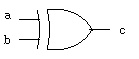 a b | c
----+-- c <= a xor b;
0 0 | 0
0 1 | 1 c = a ^ b;
1 0 | 1
1 1 | 0 c = xor(a,b)
Easy way to remember: "eXclusive or" not 11, or odd number of ones.
a b | c
----+-- c <= a xor b;
0 0 | 0
0 1 | 1 c = a ^ b;
1 0 | 1
1 1 | 0 c = xor(a,b)
Easy way to remember: "eXclusive or" not 11, or odd number of ones.
The basic "xor" gate:
truth table equation symbol 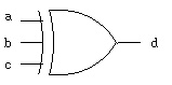 a b c | d
------+-- d <= a xor b xor c;
0 0 0 | 0
0 0 1 | 1
0 1 0 | 1 d = a ^ b ^ c;
0 1 1 | 0
1 0 0 | 1 d = xor(a,b,c)
1 0 1 | 0
1 1 0 | 0
1 1 1 | 1
Easy way to remember: odd parity, odd number of ones.
a b c | d
------+-- d <= a xor b xor c;
0 0 0 | 0
0 0 1 | 1
0 1 0 | 1 d = a ^ b ^ c;
0 1 1 | 0
1 0 0 | 1 d = xor(a,b,c)
1 0 1 | 0
1 1 0 | 0
1 1 1 | 1
Easy way to remember: odd parity, odd number of ones.
The basic "xnor" gate:
truth table equation symbol 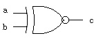 a b | c
----+-- c <= a xnor b;
0 0 | 1
0 1 | 0 c = ~ (a ^ b);
1 0 | 0
1 1 | 1 c = xnor(a,b)
Easy way to remember: "xnor" reads "not xor", equality or even parity.
a b | c
----+-- c <= a xnor b;
0 0 | 1
0 1 | 0 c = ~ (a ^ b);
1 0 | 0
1 1 | 1 c = xnor(a,b)
Easy way to remember: "xnor" reads "not xor", equality or even parity.
The basic "not" gate:
truth table equation symbol 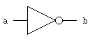 a | b
--+-- b <= not a;
0 | 1
1 | 0 b = ~ a;
b = not(a)
Easy way to remember: invert or "not", the complement.
a | b
--+-- b <= not a;
0 | 1
1 | 0 b = ~ a;
b = not(a)
Easy way to remember: invert or "not", the complement.
A specialized gate:
truth table equation symbol 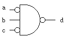 a b c | d
------+-- d <= not( not a and b and not c);
0 0 0 | 1
0 0 1 | 1
0 1 0 | 0 d = ~( ~a & b & ~c);
0 1 1 | 1
1 0 0 | 1 d = not(and(not(a),b,not(c)))
1 0 1 | 1 _______
1 1 0 | 1 _ _
1 1 1 | 1 d = (a b c)
Easy way to remember: none, just work it out.
Bubbles on the input mean the same as bubbles on the output,
invert the signal value. Often this is written with a line
_ _
above the variable d = a b c which is read:
d equals a bar and b and c bar. The word "bar" for the line
above the variable, meaning invert the variable.
It is known that there are 16 Boolean functions with two inputs.
In fact, for any number of inputs, n, there are 2^(2^n) Boolean
functions ( two to the power of two to the nth).
For n=2 16 functions 2^4
n=3 256 functions 2^8
n=4 65,536 functions 2^16
n=5 over four billion functions 2^32
The truth table for all Boolean functions of two inputs is
n x
n x a a n
o _ _ o n n o 1 1 o
a b | 0 r 2 a 4 b r d d r b 1 a 3 r 1
----+--------------------------------
0 0 | 0 1 0 1 0 1 0 1 0 1 0 1 0 1 0 1
0 1 | 0 0 1 1 0 0 1 1 0 0 1 1 0 0 1 1
1 0 | 0 0 0 0 1 1 1 1 0 0 0 0 1 1 1 1
1 1 | 0 0 0 0 0 0 0 0 1 1 1 1 1 1 1 1
Notice that for two input variables, a b, there are 2^2 = 4 rows
Notice that for four rows there are 2^4 = 16 columns.
A question is: Which are "universal" functions from which all
other functions can be obtained?
The answer is that either "nand" or "nor" can be used to create
all other functions (when having 0 and 1 available). It turns out
that electric circuits rather naturally create "nand" or "nor"
gates. No more than five "nand" gates or five "nor" gates are
needed in creating any of the 16 Boolean functions of two inputs.
Here are the circuits using only "nand" to get all 16 functions.
Example and-or logic converted to only nand logic:
fadd_v.out
Generated by program, digital logic simulator, verilog
fadd.v
There are many notations used for digital logic:
a, b, c are boolean variables:
c = a + b means c = a or b
c = ab means c = a and b
c = a * b means c = a and b
_
c = a means c = not a
c = -a means c = not a
Then, there is more than just 0 and 1 values a boolean variable may have:
H = 1 high, weak
L = 0 low, weak
X = unknown
Z = high impedance, usually open circuit, or bus
W = unknown, weak
U = uninitialized
- = don't care = X = unknown
Truth tables for and, or, ... using all VHDL std_logic signal values:
t_table.out
Generated by program, digital logic simulator, VHDL
t_table.vhdl
Similarly, for verilog
t_table_v.out
Generated by program, digital logic simulator, verilog
t_table.v
Some of these values only become useful when two gate outputs
are connected together, this may be a "wired and" or
a "wired or" depending on how the circuit is implemented
in silicone. If two wires are connected together and one
is high impedance, Z, then the other wire would control.
Also, weak will be controlled by the other wire.
You also have available logisim graphical logic simulator, see:
logisim.run
small circuit in logicsim
a b c | d
------+-- d <= not( not a and b and not c);
0 0 0 | 1
0 0 1 | 1
0 1 0 | 0 d = ~( ~a & b & ~c);
0 1 1 | 1
1 0 0 | 1 d = not(and(not(a),b,not(c)))
1 0 1 | 1 _______
1 1 0 | 1 _ _
1 1 1 | 1 d = (a b c)
Easy way to remember: none, just work it out.
Bubbles on the input mean the same as bubbles on the output,
invert the signal value. Often this is written with a line
_ _
above the variable d = a b c which is read:
d equals a bar and b and c bar. The word "bar" for the line
above the variable, meaning invert the variable.
It is known that there are 16 Boolean functions with two inputs.
In fact, for any number of inputs, n, there are 2^(2^n) Boolean
functions ( two to the power of two to the nth).
For n=2 16 functions 2^4
n=3 256 functions 2^8
n=4 65,536 functions 2^16
n=5 over four billion functions 2^32
The truth table for all Boolean functions of two inputs is
n x
n x a a n
o _ _ o n n o 1 1 o
a b | 0 r 2 a 4 b r d d r b 1 a 3 r 1
----+--------------------------------
0 0 | 0 1 0 1 0 1 0 1 0 1 0 1 0 1 0 1
0 1 | 0 0 1 1 0 0 1 1 0 0 1 1 0 0 1 1
1 0 | 0 0 0 0 1 1 1 1 0 0 0 0 1 1 1 1
1 1 | 0 0 0 0 0 0 0 0 1 1 1 1 1 1 1 1
Notice that for two input variables, a b, there are 2^2 = 4 rows
Notice that for four rows there are 2^4 = 16 columns.
A question is: Which are "universal" functions from which all
other functions can be obtained?
The answer is that either "nand" or "nor" can be used to create
all other functions (when having 0 and 1 available). It turns out
that electric circuits rather naturally create "nand" or "nor"
gates. No more than five "nand" gates or five "nor" gates are
needed in creating any of the 16 Boolean functions of two inputs.
Here are the circuits using only "nand" to get all 16 functions.
Example and-or logic converted to only nand logic:
fadd_v.out
Generated by program, digital logic simulator, verilog
fadd.v
There are many notations used for digital logic:
a, b, c are boolean variables:
c = a + b means c = a or b
c = ab means c = a and b
c = a * b means c = a and b
_
c = a means c = not a
c = -a means c = not a
Then, there is more than just 0 and 1 values a boolean variable may have:
H = 1 high, weak
L = 0 low, weak
X = unknown
Z = high impedance, usually open circuit, or bus
W = unknown, weak
U = uninitialized
- = don't care = X = unknown
Truth tables for and, or, ... using all VHDL std_logic signal values:
t_table.out
Generated by program, digital logic simulator, VHDL
t_table.vhdl
Similarly, for verilog
t_table_v.out
Generated by program, digital logic simulator, verilog
t_table.v
Some of these values only become useful when two gate outputs
are connected together, this may be a "wired and" or
a "wired or" depending on how the circuit is implemented
in silicone. If two wires are connected together and one
is high impedance, Z, then the other wire would control.
Also, weak will be controlled by the other wire.
You also have available logisim graphical logic simulator, see:
logisim.run
small circuit in logicsim
<- previous index next ->