<- previous index next ->
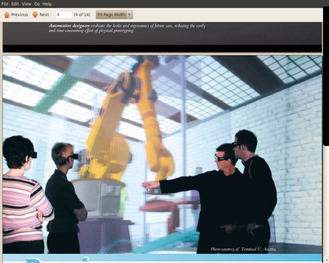
stereo 3D is here, do not get left behind
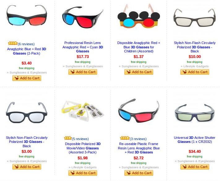 Many more types of glasses and stuff
previously we had in class 3D items that did not need glasses
Sony Blogger 3D camera
Nintdo 3DS game console
Glasses can be inexpensive, 3D screens are still expensive.
We will cover hardware and software
3-D integration and packaging could well be approaching an inflection
point. Within the past year alone, there have been several major
announcements regarding new 2.5-D, 3-D and TSV manufacturing efforts.
Certainly there are obstacles remaining, but the alternatives
available to the industry are comparatively far more challenging.
Additionally, many believe the 3-D integration approach will
ultimately offer entirely new market opportunities with new systems
capabilities beyond what is currently possible with 2-D manufacturing
approaches. There remains a natural degree of uncertainty, however,
as companies work to secure a technology position, obtain new process
and design tools, and of course, new customers and new applications.
3-D Architectures for Semiconductor Integration and Packaging
continues to give a broad, yet thorough perspective on the
techno-market opportunity and challenge offered by building devices
and systems in the vertical dimension. The format of the conference
and its presentations enables speakers to present the most up-to-date
and forthright perspectives as possible. The result is a unique forum
where one can gain critical insight into progress in the 3-D chip
arena.
autostereoscopy
We will work on 3D from the software display methods.
The latest is 3D without glasses.
Simple outline paper airplane
Makefile_plane
stereo_plane_interlaced.c
interlace_stencil.c
interlace_stencil.h
run cs437/plane/stereo_plane_interlaced
Forrest with fire
Makefile_fire
fire.c
fire_interlaced.c
fire_stereo.c
fire_image.c
fire_image.h
interlace_stencil.c
interlace_stencil.h
stereoproj.c
s128.rgb
tree2.rgb
run cs437/file/fire
wiki RealD
local wiki RealD
RealD.com products and information
technical light polarization
 images/RealD1.jpg
Dolby 3D vs Real-D
Chapter 6 of our Textbook: Interactive Computer Graphics, gives the
definitions and equations for doing lighting in any language on
any graphics platform. Programming these yourself is often a project
in CMSC 435, Computer Graphics. Many graphics toolkits implement
the lighting models for reasonably convenient use.
The physics:
Light is electro magnetic radiation. Each color has a wavelength.
We are interested in the visible spectrum between infrared
and ultraviolet. From long ago, Roy G Biv, Red, orange, yellow,
Green, Blue, indigo, violet. RGB are the electronic primary colors.
The human eye can detect the intensity and wavelength of light.
White light is all colors, black is no colors.
In ambient white light, an object looks red because the object
is reflecting light with wavelengths near red and absorbing light
at other wavelengths
Graphics definitions:
Ambient light: comes from no specific source, exists in all directions.
Diffuse light: has a point source, strikes the surface of an object at
some angle, reflects or is absorbed by an object, the
amount of reflected light depends on the incident angle
and the normal to the surface.
Specular reflection: comes from point source light reflected to a pixel
based on the angle of incidence and angle of
reflection, and takes into account the shininess
of an object. This produces a highlight or bright spot.
An object is said to have a surface material and that material can
have Ambient, Diffuse and Specular properties (for each primary color).
Example programs covered: (execute and observe lighting)
planets.c
SphereMotion.java
SphereMotion.jpg
SphereMotion.html
teapots.c
teapots.jpg
The lighting environment is the physical objects in the truncated
tetrahedron plus the light(s) that may be outside this volume.
(also see textbook 5.5)
images/RealD1.jpg
Dolby 3D vs Real-D
Chapter 6 of our Textbook: Interactive Computer Graphics, gives the
definitions and equations for doing lighting in any language on
any graphics platform. Programming these yourself is often a project
in CMSC 435, Computer Graphics. Many graphics toolkits implement
the lighting models for reasonably convenient use.
The physics:
Light is electro magnetic radiation. Each color has a wavelength.
We are interested in the visible spectrum between infrared
and ultraviolet. From long ago, Roy G Biv, Red, orange, yellow,
Green, Blue, indigo, violet. RGB are the electronic primary colors.
The human eye can detect the intensity and wavelength of light.
White light is all colors, black is no colors.
In ambient white light, an object looks red because the object
is reflecting light with wavelengths near red and absorbing light
at other wavelengths
Graphics definitions:
Ambient light: comes from no specific source, exists in all directions.
Diffuse light: has a point source, strikes the surface of an object at
some angle, reflects or is absorbed by an object, the
amount of reflected light depends on the incident angle
and the normal to the surface.
Specular reflection: comes from point source light reflected to a pixel
based on the angle of incidence and angle of
reflection, and takes into account the shininess
of an object. This produces a highlight or bright spot.
An object is said to have a surface material and that material can
have Ambient, Diffuse and Specular properties (for each primary color).
Example programs covered: (execute and observe lighting)
planets.c
SphereMotion.java
SphereMotion.jpg
SphereMotion.html
teapots.c
teapots.jpg
The lighting environment is the physical objects in the truncated
tetrahedron plus the light(s) that may be outside this volume.
(also see textbook 5.5)
 The components of light that the user sees is intensity, I, of
the primary colors RGB.
Irgb = Iambient + Idiffuse + Ispecular [clamped to 1.0 maximum each color]
(see text book 6.1-6.5)
The intensity of a pixel on the display is computed independently
for each primary color. Each intensity is the result of light on
the material of the object being reflected to the pixel on the
display screen. For the following we assume the material on the
object has been defined to provide the reflectivity of each primary
color for ambient reflection, diffuse reflection, specular reflection
and shininess. We assume that ambient light has been defined with
the amount of light for each primary color. We assume that one or more
point lights have been defined at some position with the amount of
light for each primary color. All lights and reflectivities are
assumed converted to the range 0.0 to 1.0. Any undefined value is
considered to be 0.0.
The intensity for each color is computer by the formulas:
Iambient = Kambient * Lambient
Kambient is the materials reflectivity to each color
Lambient is the amount of ambient light for each color
Idiffuse = Kdiffuse (Lvector dot Nvector) Ldiffuse
Kdiffuse is the materials reflectivity to each color
Ldiffuse is the amount of one point light for each color
Lvector is the vector from the point light to the surface
Nvector is the normal vector at the surface
the dot product computes the cosine of the angle between vectors
Ispectral = Kspecular (Rvector dot Vvector)^alpha Lspecular
Kspecular is the materials reflectivity to each color
Lspecular is the amount of one point light for each color
alpha is the exponent of the dot product, typically 20 to 100
alpha can be derived from the amount of shininess of the object
Rvector is the reflection vector
Vvector is the vector to the eye
(actual computation uses a transformation, Hvector)
A few examples:
red light amount red reflectivity result intensity
0.0 0.0 0.0
0.0 1.0 0.0
1.0 0.0 0.0
1.0 1.0 1.0
0.5 0.5 0.25
1.00^50 = 1.0
0.99^20 = 0.8 alpha = 20 at angle T, 0.99 = cos(T)
0.95^20 = 0.35
0.99^50 = 0.6 alpha = 50
0.95^50 = 0.076
teapots includes both lighting and texturing, which
are both closely related to how people interpret,
visualize, the display of graphical objects.
Texturing is covered more in the next lecture.
light_dat.c
light_dat2.c show faces
light_dat3.c show vertices
datread.c reads .dat and .det files
datread.h
drop.dat Utah .dat or .det formats
skull.dat example
skull.jpg rendered as brass
bull.dat example many vertices, surfaces
bull.jpg rendered as brass
There are many 3D graphical images available from the Utah project(s).
The .det format uses binary IEEE floating point and binary "C"
integers for fast input. The .dat format is exactly the same
numeric values encoded as ASCII text readable by "C" fscanf or
equivalent.
When you can see the object on the screen with lighting,
there has been a z-plane rendering or ray trace rendering
to convert the vertices and faces to a smooth looking object.
planets.c Lighted extension of planet.c
This demonstrates putting a light inside an object to give somewhat an
illusion of a glowing object.
Compare above to planet.c
Then optical illusions:
The components of light that the user sees is intensity, I, of
the primary colors RGB.
Irgb = Iambient + Idiffuse + Ispecular [clamped to 1.0 maximum each color]
(see text book 6.1-6.5)
The intensity of a pixel on the display is computed independently
for each primary color. Each intensity is the result of light on
the material of the object being reflected to the pixel on the
display screen. For the following we assume the material on the
object has been defined to provide the reflectivity of each primary
color for ambient reflection, diffuse reflection, specular reflection
and shininess. We assume that ambient light has been defined with
the amount of light for each primary color. We assume that one or more
point lights have been defined at some position with the amount of
light for each primary color. All lights and reflectivities are
assumed converted to the range 0.0 to 1.0. Any undefined value is
considered to be 0.0.
The intensity for each color is computer by the formulas:
Iambient = Kambient * Lambient
Kambient is the materials reflectivity to each color
Lambient is the amount of ambient light for each color
Idiffuse = Kdiffuse (Lvector dot Nvector) Ldiffuse
Kdiffuse is the materials reflectivity to each color
Ldiffuse is the amount of one point light for each color
Lvector is the vector from the point light to the surface
Nvector is the normal vector at the surface
the dot product computes the cosine of the angle between vectors
Ispectral = Kspecular (Rvector dot Vvector)^alpha Lspecular
Kspecular is the materials reflectivity to each color
Lspecular is the amount of one point light for each color
alpha is the exponent of the dot product, typically 20 to 100
alpha can be derived from the amount of shininess of the object
Rvector is the reflection vector
Vvector is the vector to the eye
(actual computation uses a transformation, Hvector)
A few examples:
red light amount red reflectivity result intensity
0.0 0.0 0.0
0.0 1.0 0.0
1.0 0.0 0.0
1.0 1.0 1.0
0.5 0.5 0.25
1.00^50 = 1.0
0.99^20 = 0.8 alpha = 20 at angle T, 0.99 = cos(T)
0.95^20 = 0.35
0.99^50 = 0.6 alpha = 50
0.95^50 = 0.076
teapots includes both lighting and texturing, which
are both closely related to how people interpret,
visualize, the display of graphical objects.
Texturing is covered more in the next lecture.
light_dat.c
light_dat2.c show faces
light_dat3.c show vertices
datread.c reads .dat and .det files
datread.h
drop.dat Utah .dat or .det formats
skull.dat example
skull.jpg rendered as brass
bull.dat example many vertices, surfaces
bull.jpg rendered as brass
There are many 3D graphical images available from the Utah project(s).
The .det format uses binary IEEE floating point and binary "C"
integers for fast input. The .dat format is exactly the same
numeric values encoded as ASCII text readable by "C" fscanf or
equivalent.
When you can see the object on the screen with lighting,
there has been a z-plane rendering or ray trace rendering
to convert the vertices and faces to a smooth looking object.
planets.c Lighted extension of planet.c
This demonstrates putting a light inside an object to give somewhat an
illusion of a glowing object.
Compare above to planet.c
Then optical illusions:
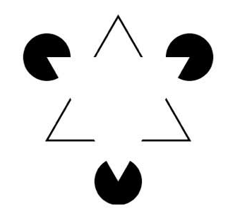 There is no white triangle.
<- previous index next ->
Many web sites on Java GUI, AWT, Swing, etc.
Many web sites on Python wx, tk, qt, etc.