<- previous index next ->
It may take a sequence of files to get the final 3D printer object you want.
This page shows what I used to get a pipe curved into a toroid.
In addition to getting the correct shape of an object, covered in triangles,
the normal vector from every triangle must point into the object.
The normal vector for the top of the object must point down.
The normal vector for the bottom of the object must point up.
The normal vector for the outside of the object must point in.
The normal vector to a triangle with points P1, P2, P3 each with x,y,z is:
ax = P3 x - P2 x length from P3 to P2
ay = P3 y - P2 y P1
az = P3 z - P2 z / \ Taking points clockwise
bx = P2 x - P1 x length from P2 to P1 / \ reverses the direction of
by = P2 y - P1 y P3____P2 the normal from counter
bz = P2 z - P1 z clockwise. The code shown
nx = ay*bz-az*by direction of normal is for counter clockwise
ny = az*bx-ax*bz normal.
nz = ax*by-ay*bx
s = sqrt(nx*nx+ny*ny+nz*nz) standard to make the length of normal vector 1.0
nx = nx / s final vector normal to triangle
ny = ny / s
nz = nz / s # see code for tri4 and tri4r to make .dat file
The code in java, given P1 x in v[0][0], P1 y in v[0][1], P1 z in v[0][2]
P2 in v[1], P3 in v[2] computes the normal vector nx, ny, nz.
ax = v[2][0] - v[1][0];
ay = v[2][1] - v[1][1];
az = v[2][2] - v[1][2];
bx = v[1][0] - v[0][0];
by = v[1][1] - v[0][1];
bz = v[1][2] - v[0][2];
nx = ay*bz-az*by;
ny = az*bx-ax*bz;
nz = ax*by-ay*bx;
s = Math.sqrt(nx*nx+ny*ny+nz*nz);
nx = nx / s;
ny = ny / s;
nz = nz / s;
The code sequence and output is:
Base just inside, outside, top and bottom to get normal in correct direction
cyl1_base.java
cyl1_base.dat
cyl1_base.stl
The code sequence and output to get a short pipe is:
cyl1_pipe.java
cyl1_pipe.dat
cyl1_pipe.stl
The code sequence and output to slope the pipe is:
cyl1_slop.java
cyl1_slop.dat
cyl1_slop.stl
The code sequence and output to curve the pipe 360 degrees,
first try to get inside, outside and just bottom, 8 bends,
and thus just the upper half, make two and glue together, is:
hcyl1_curv8.java
hcyl1_curv8.dat
hcyl1_curv8.stl
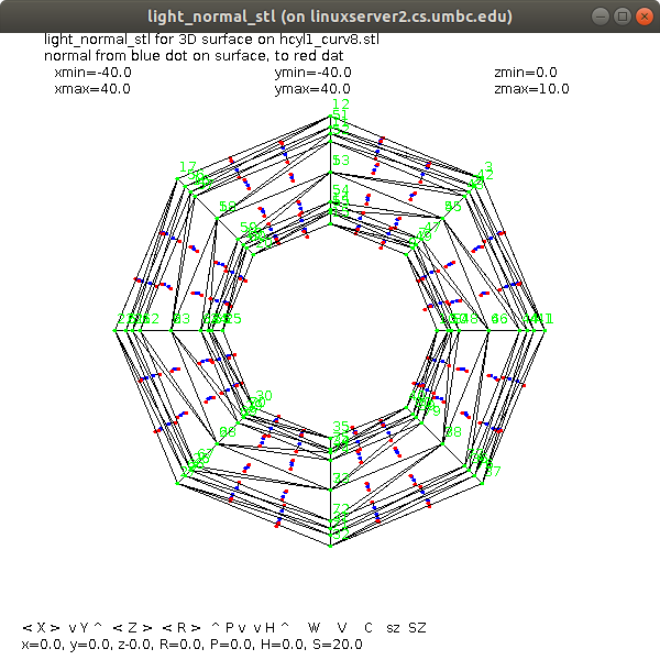
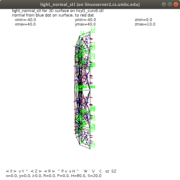 rotated 90 degrees to see direction of normal vectors
The code sequence and output for 16 bends, smoother, is:
hcyl1_curv16.java
hcyl1_curv16.dat
hcyl1_curv16.stl
The code sequence and output for 32 bends, smoother is:
hcyl1_curv.java
hcyl1_curv.dat
hcyl1_curv.stl
Having a .stl file, you can compute area and volume of the object:
read_stl.java
volume_stl.java
volume_stl_java.out
bound1a.stl
volume_stl_cube1.out
cube1.stl
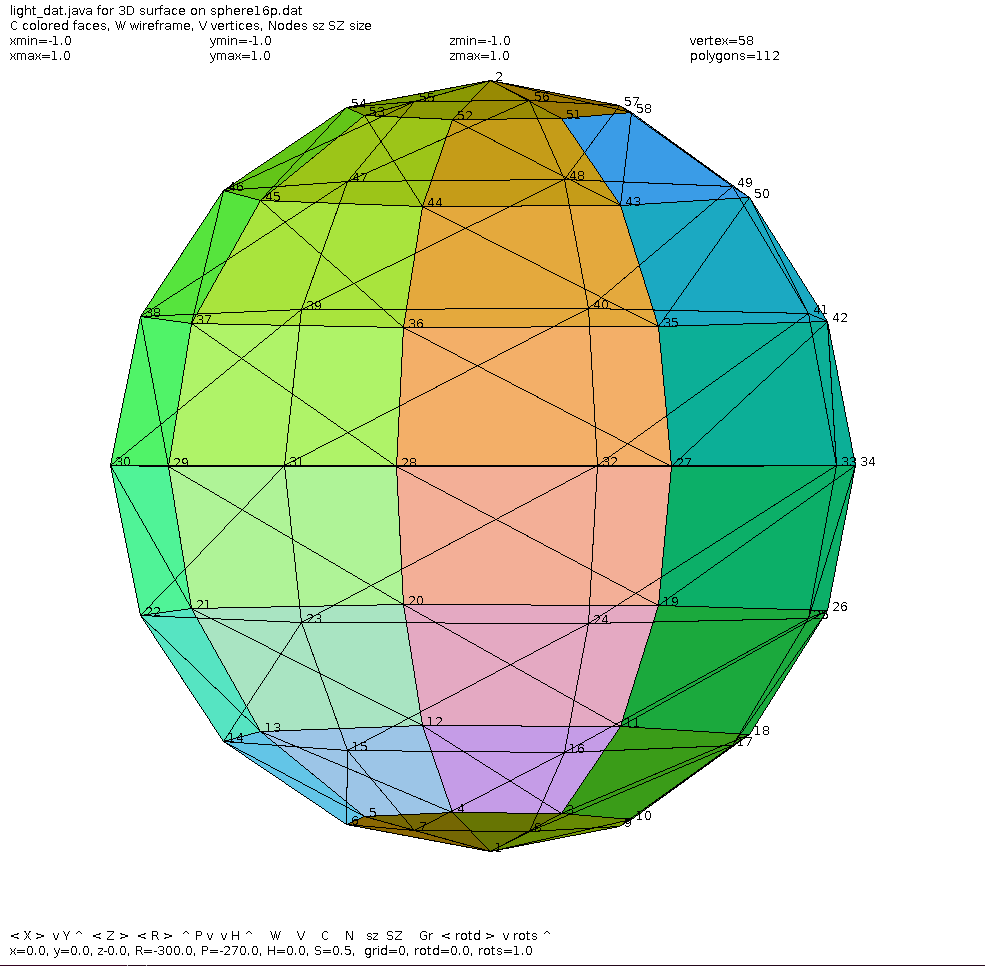
Make a sphere for 3D printer
sphere_dat.py3
sphere_dat_py3.out
sphere16p.dat
light_dat sphere16p.dat
rotated 90 degrees to see direction of normal vectors
The code sequence and output for 16 bends, smoother, is:
hcyl1_curv16.java
hcyl1_curv16.dat
hcyl1_curv16.stl
The code sequence and output for 32 bends, smoother is:
hcyl1_curv.java
hcyl1_curv.dat
hcyl1_curv.stl
Having a .stl file, you can compute area and volume of the object:
read_stl.java
volume_stl.java
volume_stl_java.out
bound1a.stl
volume_stl_cube1.out
cube1.stl
Make a sphere for 3D printer
sphere_dat.py3
sphere_dat_py3.out
sphere16p.dat
light_dat sphere16p.dat
 use dat_to_stl sphere16p.dat sphere16p.stl and make 3D object, or
sphere_stl.py3
sphere_stl_py3.out
sphere16p.stl
files:
light_dat.java source code
light_stl.java source code
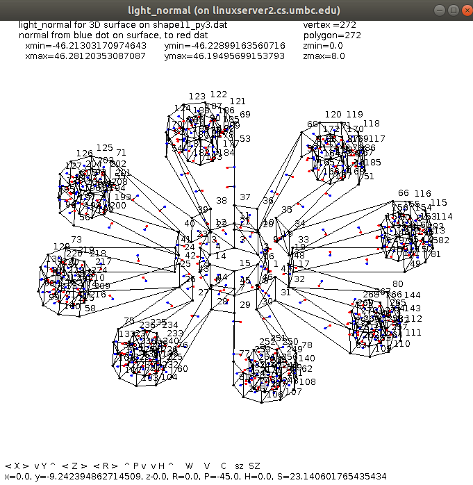
light_normal.java source code
dat_to_stl.java source code
datread.java source code
datwrite.java source code
It is better to make two half spheres and glue them together.
Utility programs to modify .dat files include:
zero_z_dat.py3 keep only z=0 and z positive
invert_z_dat.py3 negate all z values
x_to_z_dat.py3 swap x and z values
y_to_z_dat.py3 swap y and z values
Example of object made with my 3D printer
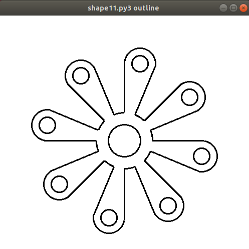
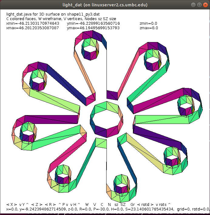
One of many "shape" files
shape11.py3 source code
shape11_py3.dat .dat output
shape11_py3.stl .stl output
outline of 3D object printed by
use dat_to_stl sphere16p.dat sphere16p.stl and make 3D object, or
sphere_stl.py3
sphere_stl_py3.out
sphere16p.stl
files:
light_dat.java source code
light_stl.java source code
light_normal.java source code
dat_to_stl.java source code
datread.java source code
datwrite.java source code
It is better to make two half spheres and glue them together.
Utility programs to modify .dat files include:
zero_z_dat.py3 keep only z=0 and z positive
invert_z_dat.py3 negate all z values
x_to_z_dat.py3 swap x and z values
y_to_z_dat.py3 swap y and z values
Example of object made with my 3D printer
One of many "shape" files
shape11.py3 source code
shape11_py3.dat .dat output
shape11_py3.stl .stl output
outline of 3D object printed by
 light_dat coloring enclosing surfaces
 light_normal of shape11.dat
all of surface is triangles with normal vector pointing inside
my Dremmel software to make gcode file did not need
bottom or top Z surface
light_normal of shape11.dat
all of surface is triangles with normal vector pointing inside
my Dremmel software to make gcode file did not need
bottom or top Z surface
 make file for creating the .stl
make_shape11 my makefile
make file for creating the .stl
make_shape11 my makefile
<- previous index next ->
Many web sites on Java GUI, AWT, Swing, etc.
Many web sites on Python wx, tk, qt, etc.