<- previous index next ->
VHDL is used for structural and functional modeling
of digital circuits.
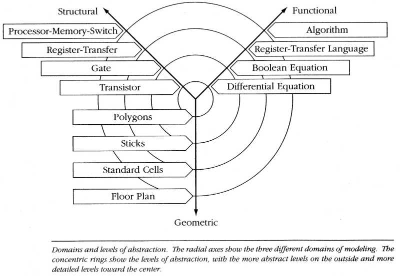 The geometric modeling is handled by other Cadence programs.
First, simple VHDL statements for logic gates:
logic gates and corresponding VHDL statements
VHDL comments start with -- acting like C++ and Java //
VHDL like C++ and Java end statements with a semicolon ;
VHDL uses "library" and "use" where C++ uses #include Java uses import
VHDL uses ".all" where Java uses ".*"
VHDL uses names similar to Pascal, case insensitive, var is same as Var, VAR
VHDL has a two part basic structure for each circuit
that is more than one gate, the "entity" and the "architecture".
There needs to be a "library" and "use" for features that are used.
The word "port" is used to mean interface.
The term "std_logic" is a type used for one bit.
The term "std_logic_vector" is a type used for more than one bit.
The time from an input changing to when the output may change
is optional. "after 1 ps" indicates 1 pico second.
"after 2 ns" indicates 2 nano seconds.
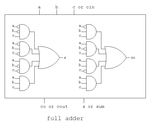
This circuit is coded as a full adder component in VHDL:
The geometric modeling is handled by other Cadence programs.
First, simple VHDL statements for logic gates:
logic gates and corresponding VHDL statements
VHDL comments start with -- acting like C++ and Java //
VHDL like C++ and Java end statements with a semicolon ;
VHDL uses "library" and "use" where C++ uses #include Java uses import
VHDL uses ".all" where Java uses ".*"
VHDL uses names similar to Pascal, case insensitive, var is same as Var, VAR
VHDL has a two part basic structure for each circuit
that is more than one gate, the "entity" and the "architecture".
There needs to be a "library" and "use" for features that are used.
The word "port" is used to mean interface.
The term "std_logic" is a type used for one bit.
The term "std_logic_vector" is a type used for more than one bit.
The time from an input changing to when the output may change
is optional. "after 1 ps" indicates 1 pico second.
"after 2 ns" indicates 2 nano seconds.
This circuit is coded as a full adder component in VHDL:
 library IEEE;
use IEEE.std_logic_1164.all;
entity fadd is -- full adder stage, interface
port(a : in std_logic;
b : in std_logic;
cin : in std_logic;
s : out std_logic;
cout : out std_logic);
end entity fadd;
architecture circuits of fadd is -- full adder stage, body
begin -- circuits of fadd
s <= a xor b xor cin after 1 ps;
cout <= (a and b) or (a and cin) or (b and cin) after 1 ps;
end architecture circuits; -- of fadd
Notice that entity fadd is ... end entity fadd; is a statement
Notice that architecture circuits of fadd is ... end architecture circuits;
is a statement. The "of fadd" connects the architecture to the entity.
The arbitrary signal names a, b, cin, s, cout were required to
be assigned a type, std_logic in this case, before being used.
Typical for many programming languages.
Now, use a loop to combine 32 fadd into a 32 bit adder:
Note: to use fadd , a long statement must be used
a0: entity WORK.fadd port map(a(0), b(0), cin, sum(0), c(0));
A unique label a0 followed by a colon :
Then entity WORK.fadd naming the entity to be used in WORK library.
Then port map( with actual signals for a, b, cin, s, cout )
Note subscripts for bit numbers in parenthesis, not [] .
The first and last stage are slightly different from the 30
stages in the loop.
add32.vhdl using the fadd above
Another variation of an adder, propagate generate.
library IEEE;
use IEEE.std_logic_1164.all;
entity fadd is -- full adder stage, interface
port(a : in std_logic;
b : in std_logic;
cin : in std_logic;
s : out std_logic;
cout : out std_logic);
end entity fadd;
architecture circuits of fadd is -- full adder stage, body
begin -- circuits of fadd
s <= a xor b xor cin after 1 ps;
cout <= (a and b) or (a and cin) or (b and cin) after 1 ps;
end architecture circuits; -- of fadd
Notice that entity fadd is ... end entity fadd; is a statement
Notice that architecture circuits of fadd is ... end architecture circuits;
is a statement. The "of fadd" connects the architecture to the entity.
The arbitrary signal names a, b, cin, s, cout were required to
be assigned a type, std_logic in this case, before being used.
Typical for many programming languages.
Now, use a loop to combine 32 fadd into a 32 bit adder:
Note: to use fadd , a long statement must be used
a0: entity WORK.fadd port map(a(0), b(0), cin, sum(0), c(0));
A unique label a0 followed by a colon :
Then entity WORK.fadd naming the entity to be used in WORK library.
Then port map( with actual signals for a, b, cin, s, cout )
Note subscripts for bit numbers in parenthesis, not [] .
The first and last stage are slightly different from the 30
stages in the loop.
add32.vhdl using the fadd above
Another variation of an adder, propagate generate.
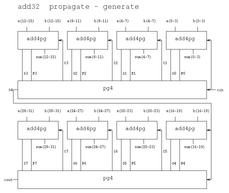 add32pg_start.vhdl for HW4
A "main" entity to use the component add32 with test data.
Note: just structure of "entity" then big architecture
entity tadd32 is -- test bench for add32.vhdl
end tadd32; -- no requirement to use "main"
architecture circuits of tadd32 is ...
tadd32.vhdl for main entity for HW4
The additional file tadd32.run was needed to tell the VHDL
simulator how long to run:
tadd32.run used to stop simulation
output of cadence simulation
The cadence output from the write statements in tadd32.vhdl is:
tadd32.chk output of tadd32.vhdl
The GHDL output from the write statements in tadd32.vhdl is:
tadd32.chkg output of tadd32.vhdl
The command line commands for using cadence are:
run_ncvhdl.bash -v93 -messages -linedebug -cdslib ~/cs411/vhdl2/cds.lib -hdlvar ~/cs411/vhdl2/hdl.var -smartorder add32.vhdl tadd32.vhdl
run_ncelab.bash -v93 -messages -access rwc -cdslib ~/cs411/vhdl2/cds.lib -hdlvar ~/cs411/vhdl2/hdl.var tadd32
run_ncsim.bash -input tadd32.run -batch -logfile tadd32.out -messages -cdslib ~/cs411/vhdl2/cds.lib -hdlvar ~/cs411/vhdl2/hdl.var tadd32
Or use make -f Makefile_411 tadd32.out
diff -iw tadd32.out tadd32.chk
The command line commands for using GHDL are:
ghdl -a --ieee=synopsys add32.vhdl
ghdl -a --ieee=synopsys tadd32.vhdl
ghdl -e --ieee=synopsys tadd32
ghdl -r --ieee=synopsys tadd32 --stop-time=65ns > tadd32.gout
diff -iw tadd32.gout tadd32.chkg
Or use make -f Makefile_ghdl tadd32.gout
output of simulation
Use a Makefile for sets of commands. You will be running more than once
to get homework and projects correct.
I provide a Makefile_411 for cadence and Makefile_ghdl for GHDL.
Browse and use as a reference for HW4, HW6, and Project.
You must do the setup exactly as stated in HW4
Sample designs and corresponding VHDL code
VHDL Language Compact Summary
The setup for HW4, HW6 and Project will be covered in the next lecture.
You will be using command lines in a terminal window on linux.gl.umbc.edu
You are given a cs411.tar file that creates the needed directories for Cadence.
Makefile_ghdl sets up Makefile for GHDL.
You will be modifying a Makefile for HW4, HW6, and Project parts.
The basic VHDL commands are shown in the Makefile's
Makefile_411 for Cadence
Makefile_ghdl for GHDL
add32pg_start.vhdl for HW4
A "main" entity to use the component add32 with test data.
Note: just structure of "entity" then big architecture
entity tadd32 is -- test bench for add32.vhdl
end tadd32; -- no requirement to use "main"
architecture circuits of tadd32 is ...
tadd32.vhdl for main entity for HW4
The additional file tadd32.run was needed to tell the VHDL
simulator how long to run:
tadd32.run used to stop simulation
output of cadence simulation
The cadence output from the write statements in tadd32.vhdl is:
tadd32.chk output of tadd32.vhdl
The GHDL output from the write statements in tadd32.vhdl is:
tadd32.chkg output of tadd32.vhdl
The command line commands for using cadence are:
run_ncvhdl.bash -v93 -messages -linedebug -cdslib ~/cs411/vhdl2/cds.lib -hdlvar ~/cs411/vhdl2/hdl.var -smartorder add32.vhdl tadd32.vhdl
run_ncelab.bash -v93 -messages -access rwc -cdslib ~/cs411/vhdl2/cds.lib -hdlvar ~/cs411/vhdl2/hdl.var tadd32
run_ncsim.bash -input tadd32.run -batch -logfile tadd32.out -messages -cdslib ~/cs411/vhdl2/cds.lib -hdlvar ~/cs411/vhdl2/hdl.var tadd32
Or use make -f Makefile_411 tadd32.out
diff -iw tadd32.out tadd32.chk
The command line commands for using GHDL are:
ghdl -a --ieee=synopsys add32.vhdl
ghdl -a --ieee=synopsys tadd32.vhdl
ghdl -e --ieee=synopsys tadd32
ghdl -r --ieee=synopsys tadd32 --stop-time=65ns > tadd32.gout
diff -iw tadd32.gout tadd32.chkg
Or use make -f Makefile_ghdl tadd32.gout
output of simulation
Use a Makefile for sets of commands. You will be running more than once
to get homework and projects correct.
I provide a Makefile_411 for cadence and Makefile_ghdl for GHDL.
Browse and use as a reference for HW4, HW6, and Project.
You must do the setup exactly as stated in HW4
Sample designs and corresponding VHDL code
VHDL Language Compact Summary
The setup for HW4, HW6 and Project will be covered in the next lecture.
You will be using command lines in a terminal window on linux.gl.umbc.edu
You are given a cs411.tar file that creates the needed directories for Cadence.
Makefile_ghdl sets up Makefile for GHDL.
You will be modifying a Makefile for HW4, HW6, and Project parts.
The basic VHDL commands are shown in the Makefile's
Makefile_411 for Cadence
Makefile_ghdl for GHDL
<- previous index next ->