<- previous index next ->
Debugging VHDL (or almost any computer input)
1) Expect errors. Nobody's perfect.
2) Automate to make it easy to re-run, e.g. Makefile_411 or Makefile_ghdl
for HW4, you may use either or both.
make -f Makefile_411 tadd32.out # cadence
diff -iw tadd32.out tadd32.chk
make -f Makefile_ghdl tadd32.gout # GHDL diff in Makefile_ghdl
diff -iw tadd32.gout tadd32.chkg
The .out and .gout differ in extra lines, vhdl output should be the same.
Use Makefile or do a lot of typing: for cadence
run_ncvhdl.bash -v93 -messages -linedebug -cdslib ~/cs411/vhdl2/cds.lib -hdlvar ~/cs411/vhdl2/hdl.var -smartorder add32.vhdl tadd32.vhdl
run_ncelab.bash -v93 -messages -access rwc -cdslib ~/cs411/vhdl2/cds.lib -hdlvar ~/cs411/vhdl2/hdl.var tadd32
run_ncsim.bash -input tadd32.run -batch -logfile tadd32.out -messages -cdslib ~/cs411/vhdl2/cds.lib -hdlvar ~/cs411/vhdl2/hdl.var tadd32
Use Makefile or do a lot of typing: for GHDL
ghdl -a --ieee=synopsys add32.vhdl
ghdl -a --ieee=synopsys tadd32.vhdl
ghdl -e --ieee=synopsys tadd32
ghdl -r --ieee=synopsys tadd32 --stop-time=65ns > tadd32.gout
diff -iw tadd32.gout tadd32.chkg
3) for rest HW6, part1, part2a, part2b, part3a, part3b
HW6
make -f Makefile_411 pmull16_test.out # cadence
diff -iw pmul16_test.out pmul16.chk
make -f Makefile_ghdl tadd32.gout # GHDL
diff -iw pmul16_test.gout pmul16.chkg
part1
make -f Makefile_411 part1.out # cadence
diff -iw part1.out part1.chk
make -f Makefile_ghdl part1.gout # GHDL
diff -iw part1.gout part1.chkg
part2a
make -f Makefile_411 part2a.out # cadence
diff -iw part2a.out part2a.chk
make -f Makefile_ghdl part2a.gout # GHDL
diff -iw part2a.gout part2a.chkg
part2b
make -f Makefile_411 part2b.out # cadence
diff -iw part2b.out part2b.chk
make -f Makefile_ghdl part2b.gout # GHDL
diff -iw part2b.gout part2b.chkg
part3a
make -f Makefile_411 part3a.out # cadence
diff -iw part3a.out part3a.chk
make -f Makefile_ghdl part3a.gout # GHDL
diff -iw part3a.gout part3a.chkg
part3b
make -f Makefile_411 part3b.out # cadence
diff -iw part3b.out part3b.chk
make -f Makefile_ghdl part3b.gout # GHDL
diff -iw part3b.gout part3b.gchk
4) FIX THE FIRST ERROR !!!!
Yes, you can fix other errors also, but one error can cause
a cascading effect and produce many errors.
Don't panic when there was only one error, you fixed that,
then the next run you get 37 errors. The compiler has stages,
it stops on a stage if there is an error. Fixing that error
lets the compiler move to the next stage and check for other
types of errors. Go to step 3)
5) Don't give up. Don't make wild guesses. Do experiment with
one change at a time. You may actually have to read some
of the lectures :)
6) Your circuit compiles and simulates but the output is not
correct. Solution: find first difference, or add debug print.
OK to put in debug printout, remove or comment out before submit.
Most circuits in this course have a print process. You can
easily add printout of more signals. Look for the existing
code that has 'write' and 'writeline' statements.
To print out some signal, xxx, after a 'writeline' statement add
write(my_line, string'(" xxx=")); -- label printout
hwrite(my_line, xxx); -- hex for long signals
write(my_line, string'(" enb="));
write(my_line, enb); -- bit for single values
writeline(output, my_line); -- outputs line
7) You have a signal, xxx, that seems to be wrong and you can not
find when it gets the wrong value. OK, create a new process to
print every change and when it occurs.
prtxxx: process (xxx)
variable my_line : LINE; -- my_line needs to be defined
begin
write(my_line, string'("xxx="));
write(my_line, xxx); -- or hwrite for long signals
write(my_line, string'(" at="));
write(my_line, now); -- "now" is simulation time
writeline(output, my_line); -- outputs line
end process prtxxx;
When adding 'write' statements, you may need to add the
context clause in front of the enclosing design unit. e.g.
library STD;
use STD.textio.all; -- defines LINE, writeline, etc.
library IEEE;
use IEEE.std_logic_1164.all;
use IEEE.std_logic_textio.all; -- defines write on std_logic (_vector)
8) Read your code.
Every identifier must be declared before it is used.
Every signal MUST be set exactly once, e.g.
xxx <= a;
xxx <= b; -- somewhere else, BAD !
-- all hardware runs all the time
-- the ordering of some statements does not matter
a0: fadd port map(a(0), b(0), cin , sum(0), c(0));
a1: fadd port map(a(1), b(1), c(0), sum(1), c(0));
#### BAD !
Signals must match in type and size. An error having
"shape mismatch" means incompatible size. You can not put
one bit into a 32 bit signal nor 32 bits into a one bit signal.
"...type... error" Are you putting an integer into a std_logic?
You can not put an identifier of type std_logic into
std_logic_vector. a(31 downto 28) is of type std_logic_vector,
a(31) is of type std_logic.
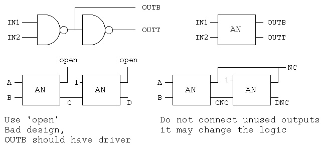
Everywhere a specific signal name is used, these points are
wired together. For VHDL simulation purposes, all points on a
wire always have exactly the same value. Zero propagation delay
through a wire. Be careful what you wire together. Use the VHDL
reserved word 'open' for open circuits rather than NC for
no connection.
 ncsim: 05.40-s011: (c) Copyright 1995-2005 Cadence Design Systems, Inc.
ncsim> run 7 ns
A= 1 B= 1 C= U D= U CNC= U DNC= U NC= U at time 0 ns
A= 1 B= 1 C= U D= U CNC= U DNC= U NC= U at time 1 ns
A= 1 B= 1 C= 1 D= U CNC= U DNC= U NC= U at time 2 ns
A= 1 B= 1 C= 1 D= U CNC= U DNC= U NC= U at time 3 ns
A= 1 B= 1 C= 1 D= 1 CNC= U DNC= U NC= U at time 4 ns
A= 1 B= 1 C= 1 D= 1 CNC= U DNC= U NC= U at time 5 ns
A= 1 B= 1 C= 1 D= 1 CNC= U DNC= U NC= U at time 6 ns
Ran until 7 NS + 0
ncsim> exit
!!! !!! never set due to connection
-- use_open.vhdl
library IEEE;
use IEEE.std_logic_1164.all;
entity AN is
port(IN1 : in std_logic;
IN2 : in std_logic;
OUTB : inout std_logic; -- because used internally, bad design
OUTT : out std_logic);
end entity AN;
architecture circuits of AN is
begin -- circuits
OUTB <= IN1 nand IN2 after 1 ns;
OUTT <= not OUTB after 1 ns;
end architecture circuits; -- of AN
library IEEE;
use IEEE.std_logic_1164.all;
use STD.textio.all;
use IEEE.std_logic_textio.all;
entity use_open is
end entity use_open;
architecture circuits of use_open is
signal A : std_logic := '1';
signal B : std_logic := '1';
signal C, CNC : std_logic;
signal D, DNC : std_logic;
signal NC : std_logic := '1'; -- for no connection or tied off
begin
my_print : process is
variable my_line : line;
begin
write(my_line, string'("A= "));
write(my_line, A);
write(my_line, string'(" B= "));
write(my_line, B);
write(my_line, string'(" C= "));
write(my_line, C);
write(my_line, string'(" D= "));
write(my_line, D);
write(my_line, string'(" CNC= "));
write(my_line, CNC);
write(my_line, string'(" DNC= "));
write(my_line, DNC);
write(my_line, string'(" NC= "));
write(my_line, NC);
write(my_line, string'(" at time "));
write(my_line, now);
writeline(output, my_line);
wait for 1 ns;
end process my_print;
n01: entity WORK.AN port map(A, B, open, C);
n02: entity WORK.AN port map('1', C, open, D);
n03: entity WORK.AN port map(A, B, NC, CNC);
n04: entity WORK.AN port map('1', CNC, NC, DNC);
end architecture circuits; -- of use_open
Truth tables using type std_logic
t_table.vhdl
Now, some Cadence VHDL error messages.
-- error.vhdl demonstrate VHDL compiler error messages
library IEEE;
use IEEE.std_logic_1164.all;
entity AN is
port(IN1 : in std_logic;
IN2 : in std_logic;
OUTB : inout std_logic; -- because used internally
OUTT : out std_logic;);
end entity AN;
architecture circuits of AN is
signal aaa : std_logic;
begin -- circuits
OUTB <= aa and IN1 and IN2 after 1 ns;
OUTT <= not OUTB after 1 ns;
end architecture circuits; -- of AN
old output:
ncvhdl: 05.40-s011: (c) Copyright 1995-2005 Cadence Design Systems, Inc.
OUTT : out std_logic;);
|
ncvhdl_p: *E,PORNKW (error.vhdl,10|28): identifier expected.
OUTT : out std_logic;);
|
ncvhdl_p: *E,MISCOL (error.vhdl,10|28): expecting a colon (':') 87[4.3.3] 93[4.3.2].
OUTT : out std_logic;);
|
ncvhdl_p: *E,PORNKW (error.vhdl,10|31): identifier expected.
OUTT : out std_logic;);
|
ncvhdl_p: *E,MISCOL (error.vhdl,10|31): expecting a colon (':') 87[4.3.3] 93[4.3.2].
end entity AN;
|
ncvhdl_p: *E,EXPRIS (error.vhdl,11|13): expecting the reserved word 'IS' [1.1].
OUTB <= aa and IN1 and IN2 after 1 ns;
|
ncvhdl_p: *E,IDENTU (error.vhdl,16|11): identifier (AA) is not declared [10.3].
Now you are ready to tackle Homework 6
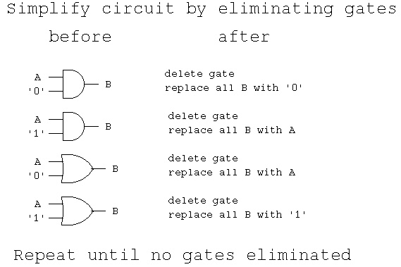
To simplify
ncsim: 05.40-s011: (c) Copyright 1995-2005 Cadence Design Systems, Inc.
ncsim> run 7 ns
A= 1 B= 1 C= U D= U CNC= U DNC= U NC= U at time 0 ns
A= 1 B= 1 C= U D= U CNC= U DNC= U NC= U at time 1 ns
A= 1 B= 1 C= 1 D= U CNC= U DNC= U NC= U at time 2 ns
A= 1 B= 1 C= 1 D= U CNC= U DNC= U NC= U at time 3 ns
A= 1 B= 1 C= 1 D= 1 CNC= U DNC= U NC= U at time 4 ns
A= 1 B= 1 C= 1 D= 1 CNC= U DNC= U NC= U at time 5 ns
A= 1 B= 1 C= 1 D= 1 CNC= U DNC= U NC= U at time 6 ns
Ran until 7 NS + 0
ncsim> exit
!!! !!! never set due to connection
-- use_open.vhdl
library IEEE;
use IEEE.std_logic_1164.all;
entity AN is
port(IN1 : in std_logic;
IN2 : in std_logic;
OUTB : inout std_logic; -- because used internally, bad design
OUTT : out std_logic);
end entity AN;
architecture circuits of AN is
begin -- circuits
OUTB <= IN1 nand IN2 after 1 ns;
OUTT <= not OUTB after 1 ns;
end architecture circuits; -- of AN
library IEEE;
use IEEE.std_logic_1164.all;
use STD.textio.all;
use IEEE.std_logic_textio.all;
entity use_open is
end entity use_open;
architecture circuits of use_open is
signal A : std_logic := '1';
signal B : std_logic := '1';
signal C, CNC : std_logic;
signal D, DNC : std_logic;
signal NC : std_logic := '1'; -- for no connection or tied off
begin
my_print : process is
variable my_line : line;
begin
write(my_line, string'("A= "));
write(my_line, A);
write(my_line, string'(" B= "));
write(my_line, B);
write(my_line, string'(" C= "));
write(my_line, C);
write(my_line, string'(" D= "));
write(my_line, D);
write(my_line, string'(" CNC= "));
write(my_line, CNC);
write(my_line, string'(" DNC= "));
write(my_line, DNC);
write(my_line, string'(" NC= "));
write(my_line, NC);
write(my_line, string'(" at time "));
write(my_line, now);
writeline(output, my_line);
wait for 1 ns;
end process my_print;
n01: entity WORK.AN port map(A, B, open, C);
n02: entity WORK.AN port map('1', C, open, D);
n03: entity WORK.AN port map(A, B, NC, CNC);
n04: entity WORK.AN port map('1', CNC, NC, DNC);
end architecture circuits; -- of use_open
Truth tables using type std_logic
t_table.vhdl
Now, some Cadence VHDL error messages.
-- error.vhdl demonstrate VHDL compiler error messages
library IEEE;
use IEEE.std_logic_1164.all;
entity AN is
port(IN1 : in std_logic;
IN2 : in std_logic;
OUTB : inout std_logic; -- because used internally
OUTT : out std_logic;);
end entity AN;
architecture circuits of AN is
signal aaa : std_logic;
begin -- circuits
OUTB <= aa and IN1 and IN2 after 1 ns;
OUTT <= not OUTB after 1 ns;
end architecture circuits; -- of AN
old output:
ncvhdl: 05.40-s011: (c) Copyright 1995-2005 Cadence Design Systems, Inc.
OUTT : out std_logic;);
|
ncvhdl_p: *E,PORNKW (error.vhdl,10|28): identifier expected.
OUTT : out std_logic;);
|
ncvhdl_p: *E,MISCOL (error.vhdl,10|28): expecting a colon (':') 87[4.3.3] 93[4.3.2].
OUTT : out std_logic;);
|
ncvhdl_p: *E,PORNKW (error.vhdl,10|31): identifier expected.
OUTT : out std_logic;);
|
ncvhdl_p: *E,MISCOL (error.vhdl,10|31): expecting a colon (':') 87[4.3.3] 93[4.3.2].
end entity AN;
|
ncvhdl_p: *E,EXPRIS (error.vhdl,11|13): expecting the reserved word 'IS' [1.1].
OUTB <= aa and IN1 and IN2 after 1 ns;
|
ncvhdl_p: *E,IDENTU (error.vhdl,16|11): identifier (AA) is not declared [10.3].
Now you are ready to tackle Homework 6
To simplify
 sqrt examples of simplify
<- previous index next ->