<- previous index next ->
Often called ALU a major part of the CPU
Quick review:
Basic digital logic
The Arithmetic Logic Unit is the section of the CPU that actually
performs add, subtract, multiply, divide, and, or, floating point and
other operations. The choice of which operations are implemented is
determined by the Instruction Set Architecture, ISA. Most modern
computers separate the integer unit from the floating point unit.
Many modern architectures have simple integer, complex integer, and
an assortment of floating point units.
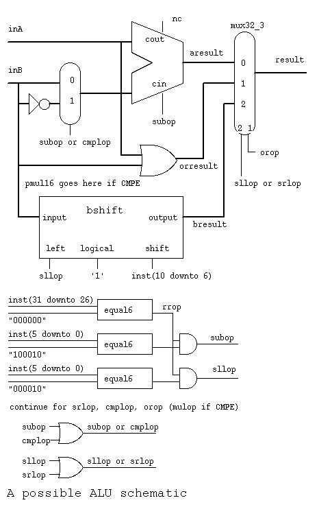 The ALU gets inputs from registers part1.jpg
Where did numbers such as 100010 for subop and 000010 for sllop
come from ? cs411_opcodes.txt
The ALU gets inputs from registers part1.jpg
Where did numbers such as 100010 for subop and 000010 for sllop
come from ? cs411_opcodes.txt
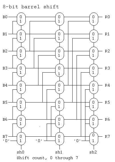
 Note that bshift.vhdl contains two different architectures
for the same entity. A behavioral architecture using sequential
programming and a circuits architecture using digital logic
components.
bshift.vhdl
An 8-bit version of shift right logical, using single bit signals,
three bit shift count, is:
Note that bshift.vhdl contains two different architectures
for the same entity. A behavioral architecture using sequential
programming and a circuits architecture using digital logic
components.
bshift.vhdl
An 8-bit version of shift right logical, using single bit signals,
three bit shift count, is:
 Where diagram said "pmul16 goes here" a parallel multiplier and
a parallel divider would be included. The "result" mux would
get two more data inputs, and two more control inputs:
mulop and divop. Then the upper half of the product and
the remainder would be saved in a temporary register,
the "hi" of the "hi" and "lo" registers shown previously.
Then stored on the next clock cycle in this architecture.
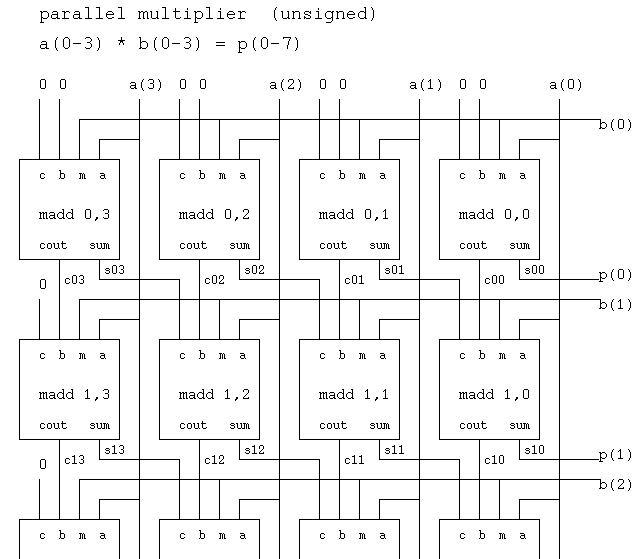
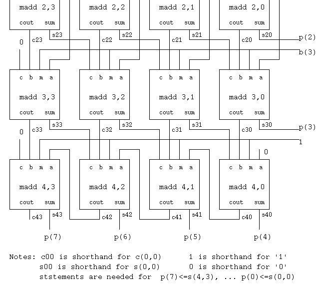
Fully parallel multiplier (possibly pipelined in another architecture)
Where diagram said "pmul16 goes here" a parallel multiplier and
a parallel divider would be included. The "result" mux would
get two more data inputs, and two more control inputs:
mulop and divop. Then the upper half of the product and
the remainder would be saved in a temporary register,
the "hi" of the "hi" and "lo" registers shown previously.
Then stored on the next clock cycle in this architecture.
Fully parallel multiplier (possibly pipelined in another architecture)
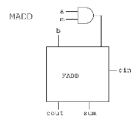 Fully parallel divider (possibly pipelined in another architecture)
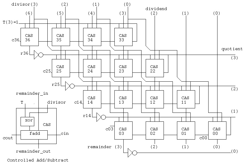 There are many ways to build an ALU. Often the choice is based
on mask making and requires a repeated pattern. The "bit slice"
method uses the same structure for every bit. One example is:
There are many ways to build an ALU. Often the choice is based
on mask making and requires a repeated pattern. The "bit slice"
method uses the same structure for every bit. One example is:
 Note that 'Operation' is two bits, 0 for logical and, 1 for logical or,
2 for add or subtract, and 3 for an operation called set used for
comparison.
'Binvert' and 'CarryIn' would be set to '1' for subtract.
'Binvert' and 'a' set to '0' would be complement.
The overflow detection is in every stage yet only used in the
last stage.
The bit slices are wired together to form a simple ALU:
Note that 'Operation' is two bits, 0 for logical and, 1 for logical or,
2 for add or subtract, and 3 for an operation called set used for
comparison.
'Binvert' and 'CarryIn' would be set to '1' for subtract.
'Binvert' and 'a' set to '0' would be complement.
The overflow detection is in every stage yet only used in the
last stage.
The bit slices are wired together to form a simple ALU:
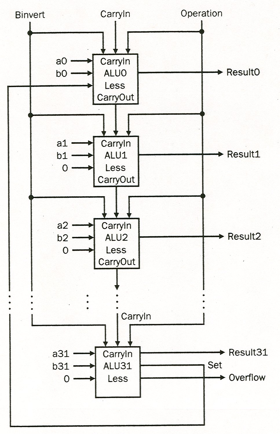 The 'set' operation would give non zero if 'a' < 'b' and
zero otherwise. A possible condition status or register
value for a "beq" instruction.
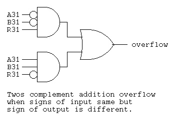
If overflow was to be detected, the circuit below uses the
sign bit of the A and B inputs and the sign bit of the
result to detect overflow on twos complement addition.
The 'set' operation would give non zero if 'a' < 'b' and
zero otherwise. A possible condition status or register
value for a "beq" instruction.
If overflow was to be detected, the circuit below uses the
sign bit of the A and B inputs and the sign bit of the
result to detect overflow on twos complement addition.
 Time to submit any outstanding projects
<- previous index next ->