|
|
| PJRC.COM Offline Archive, February 07, 2004 Visit this page on the live site |
| ||
|
Shopping Cart
|
| Home | MP3 Player | 8051 Tools | All Projects | PJRC Store | Site Map |
|
You are here:
MIDI Drum Machine
| Search PJRC |
|
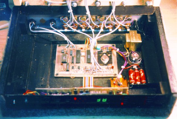
Back Panel: MIDI In, Out and Thru connectors (right side), alternate external inputs (left, bottom), and sensitivity adjustment knobs (left, top).
Center: Main circuit board.
Center right: Power supply transformer and capacitor (back), battery backup for user configuration (front), and a small breadboard that generates a reset signal (not actually used).
Front Panel: (Left to right) Power LED, "all notes off" pushbutton, 4 user-input pushbuttons (pad select, parm select, increment and decrement), currently selected pad display (8 LEDs), three digit parameter value disply, and currently selected pameter name (8 LEDs).
There is another similar inside photo, which shows a bit more of the lid and has a bit better view of the front panel, but the view of the circuitry is smaller.
Take a closer look at the circuit board.
Or go right to the main CPU schematic.