|
|
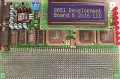
New Rev 4 Board |
A newer version (Rev 4) of
this circuit board is available. Rev 4 includes a faster CPU,
more memory, more I/O and an optional LCD. We recommend you use
Rev 4 for new projects. We are keeping these very old pages on-line
for reference to assist people who build the original version of
the 8051 development board.
The very old design is difficult to troubleshoot due to
the use of an external 27C64 EPROM for the monitor program. We highly
recommend you use the new design for any new projects.
Visual inspection really is the easiest and most time effective
way to troubleshoot in a case like this where the design is
known to work. Please check your work carefully.
The only test equipment mentioned below is a multimeter (volts/ohms)
and perhaps a clip lead to connect it's negative lead to
ground. Fancy (expensive) test equipment, such as an oscilloscope
or logic analyzer is not needed. Keep in mind that a voltmeter's
DC voltage measurement measures average voltage. A digital signal
which is 0 volts low and 5 volts high will read about 1.7 volts
if it is high 1 out of every 3 clock cycles. For non-CMOS logic,
the high output is somewhere lower, so 1.1 to 1.8 volts is probably
fine, but 0, 4.1 or 5 volts would indicate a problem.
Before inserting the chips, check for opens and shorts with an ohm meter.
This can be a tedious process, particularily for the buses. At
least check that one bus line connects to the proper pin on each
chip, so that you're sure the bus was not accidentally wired in
reverse somewhere.
Apply power without any chips in the board.
Using a DC voltmeter, verify that power is
applied to every chip correctly.
This step MUST NOT be skipped, since
chips will likely be damaged if power is not applied correctly. To
do this check, attach the negative lead to ground at the power supply,
and then probe the Vcc pin of every socket. Then connect the positive
test lead to +5 volts at the power supply and probe the ground pin
of every chip. You must do both of these tests to assure that every
chip's power is connected properly. If signals are connected incorrectly,
usually chips won't be damaged, but errors in the power connections
are usually more painful, so do this simple check before putting
the chips into their sockets.
Once the power is known to be correct, insert the MAX232 and
its capacitors. Apply power and check the voltages on the
RS-232 connector. The transmit line should be at about -8 to
-10 volts. The receive line should be at about zero volts,
though less than about 1 volt is fine. As well, pin 2 of the
MAX232 should be at about +10 volts and pin 6 should be at
about -10 volts.
Connect the voltmeter's
ground to your computer's ground and check the voltages on
the lines of the computer's serial cable. The line which will
connect the the 8051 board's receive ought to be at about -12 volts (but
it may be between -5 to -15 volts),
and the one which will connect to the 8051 board's transmit
ought to have very little voltage on it. If this is the case,
you're finally ready to try it out.
Now insert the 8051, 27C64 EPROM,
74HC08, 74HC138, 74HC373, crystal and other passive components.
Make sure that pin 1 is lines up. A chips is usually
destroyed if it is plugged in backwards, so please
double check.
Turn it on and hit carriage return if PAULMON's automatic baud
rate detection is used.
Does the welcome message appear? If you get a screenful of
garbage, try again, perhaps at a lower baud rate. 1200 baud
is a good place to start before you know if your board works.
If you get garbage with PAULMON1, you need to turn off the
power instead of just pressing reset.
If Nothing Happens When You Turn It On:
- Is the crystal oscillating? Do not probe the crystal pins,
instead check the DC (average) voltages on the PSEN and ALE pins.
According to the standard timing diagram, ALE is high 1/3 of
the time during program fetchs, and PSEN is high 1/2 of the
time. For a CMOS 8051 running at 5 volts, ALE would then
be about 1.7 volts and PSEN ought to be about 2.5 volts. For an
NMOS 8051, the voltages may be a bit lower. If these are
both stuck at either 0 or 5 volts, the oscillator probably isn't.
- Is it actually finished with reset? Check the voltage on the
reset pin. When you apply power, it should jump to five volts,
but drop to zero in only a moment. Your meter may not respond
quickly enough to show a reading of five, but you should see
it jump and it should end up at zero.
- Is it configured to access the external program memrory?
Check the EA pin. It should be low so that the 8051 will
use the program stored in the EPROM.
- Is the EPROM getting enabled? Probe the EPROM's CS pin
(pin 20). It had ought to be about nearly zero, since the
8051 should be spending nearly all its time fetching instructions
from this chip.
- What memory ranges is the 8051 accessing? Probe the address
pins, particularly A15, A14, and A13. These should all be low
voltages, since it will be executing a program from the EPROM.
Repeating patterns (visible to the human eye on a voltmeter)
often times mean the data bus is returning FF (or something
else) for all reads, and
the 8051 is just cycling through all 64k of memory doing nothing
useful. Check the wiring to the 74HC373. Are the D's and Q's
interchanged? Make sure pin 1 is held low, so it will actually
drives it's Q output pins.
- Check the EPROM's RD pin (pin 22). It should be similar
to PSEN's voltage, about 2.5 volts, perhaps less if a non-CMOS
AND gate was used.
- Are bus lines shorted together? Probe all address and data lines
looking for identical voltages.
- Probe all address lines
and touch lines with 100k resistor to ground and +5V... if this
changes the voltage much, likely open circuit. Unfortunately,
the data bus floats at times, so this test isn't as conclusive
for the data bus, but visual inspection is usually easier than
this resistor test anyways. An ohms check with the chips removed
is also easier and you don't take a chance of shorting things by
poking around while the system is turned on.
- Are all the chips properly seated in their sockets? It's
common for a pin to bend under the chip and appear to go into
the socket when viewed from the side. Look underneath the
chips from the top and bottom ends of the sockets.
- Are all the chips the right ones: Double check the numbers.
Make sure you didn't install a NAND gate intead of an AND gate!
Getting the EPROM/RAM or 8051/82C55 swapped doesn't help either.
- For wire wrap construction: Check all the wires... are any pins empty that
shouldn't be? Count the number of connections for each node on the
schematic and compare to the board.
- For print circuit board construction: Did you make the
modification which is required?
It's best to do all voltage probing
from the top side of the board directly onto chip pins, so faults in the
sockets are tested as well. Since almost all voltages are measured
with respect to ground, it pays to attach the negative probe of
your voltmeter to a secure ground point on the board. You only
have two hands...
Once The Welcome Message Appears
install ram, download a simple
test program and see if it made it into memory.
install 82C55 chips, run a simple test program to verify that they work.
 Where to go from here?
Paul's Sample 8051 Development Board Design
http://www.pjrc.com/tech/8051/dev-board-testing.html
Last updated: November 28, 2003
Statue: about 80% done now... need some photos... and proofreading
Suggestions, comments, criticisms, things you want??
<paul@pjrc.com>