|
|
New Rev 4 Board |
A newer version (Rev 4) of
this circuit board is available. Rev 4 includes a faster CPU,
more memory, more I/O and an optional LCD. We recommend you use
Rev 4 for new projects. We are keeping these very old pages on-line
for reference to assist people who build the original version of
the 8051 development board.
The very old design is difficult to troubleshoot due to
the use of an external 27C64 EPROM for the monitor program. We highly
recommend you use the new design for any new projects.
Several people have asked
how to save images.
Here's a few things to try.
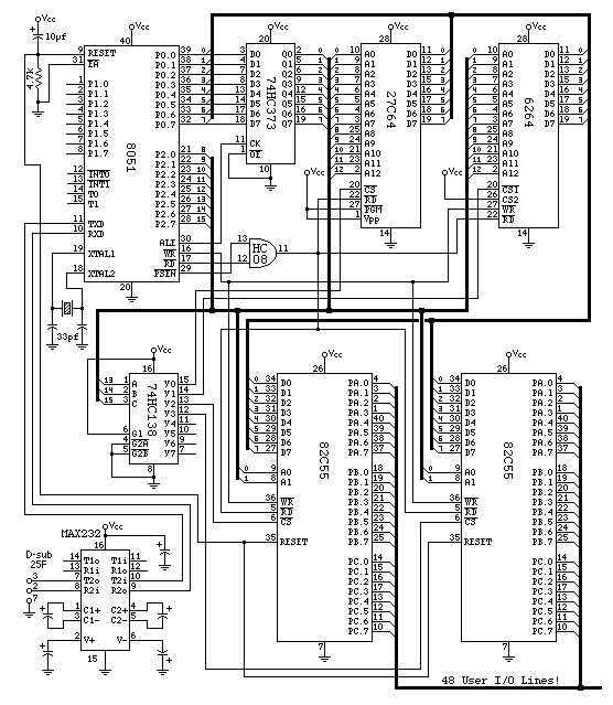
Please note, pin 3 on the '138 is actually connected to ground in the
printed circuit board layout
instead of connected to A15 as shown here. If
wire wrap construction or some
other prototype technique is used to construct the board, pin 3 should
be connected to A15 so that the other four address decoder lines may
be used for expansion. Also, the MAX232 and its support capacitors
are not included in the printed circuit board layout.
Several people have commented that the capacitor connected to pin
2 of the MAX232 chip should have it's negative terminal connected
to Vcc instead of ground. Maxim's data sheet shows the typical
application with it connected that way, presumably since you could
use a capacitor rated for only 6.3 volts rather than 16 volts.
I connect it to ground to avoid AC coupling digital switching noise
from Vcc to the charge-pump supply voltage which will drive the
rs-232 transmitters. The circuit will work either way, but if your
capacitor is rated for only 6.3 or 10 volts, better connect is as
shown in maxim's data sheet. (the cap on pin 6 still must be rated
for 16 volts though) Values aren't shown, but anything between 1uF
to 10uF should work fine. 0.1uF might work for baud rates under 19200.
 Go on to wire wrap construction
Go on to pc board construction
Paul's Sample 8051 Development Board Design
http://www.pjrc.com/tech/8051/dev-board-schematic.html
Last updated: November 28, 2003
Statue: need to finish and check this schematic.
Suggestions, comments, criticisms, things you want??
<paul@pjrc.com>