Timing Library Format (TLF)
TLF is an ASCII representation of the timing and power parameters associated with any cell in a particular semiconductor technology
The timing and power parameters are obtained by simulating the cells under a variety of conditions and the data is represented in the TLF format
The TLF file contains timing models and data to calculate
I/O path delays and timing check values are computed on a per-instance basis
Path delays in a circuit depend upon the electrical behavior of interconnects between cells
This parasitic information can be based on the layout of the design, but must be estimated when no layout information is available
Also it is not possible to predict the process, voltage and temperature variations and derating factors can be included to compensate for these variations
Cell-Based Delay Calculation
Cell-based delay calculation is modeled by characterizing
cell delay and
output transition time (output slew) as a function of
input transition time (input slew) and the
capacitive load on the output of the cell.
Timing checks are also functions of input slew and output capacitive load
Each cell has a specific number of input-to-output paths
m Path delays can be described for each input signal transition that affects an output signal
m The path delay can also depend on signals at other inputs (state dependencies)
m In many sequential cells, the path delay from an input pin to an output pin can depend on the path delay from another output pin to this output pin
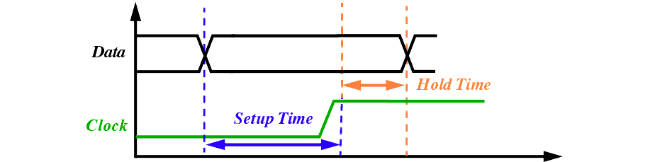
Delay Calculation and Timing Checks
Input-Slew, Output-Slew and Cell Delay
Setup and Hold Time (Timing Checks)
Delay Calculation and Timing Checks
Delay Calculation and Timing Checks
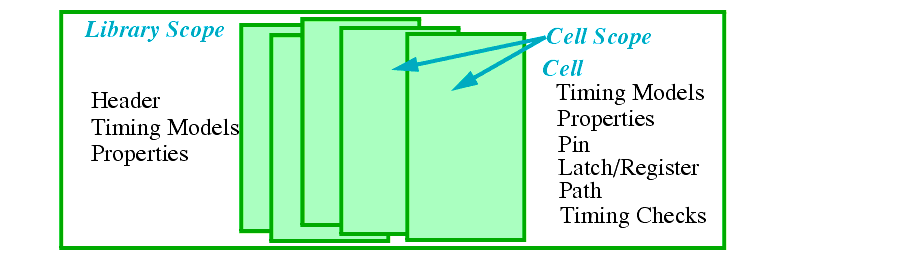
The TLF file is organized in two scopes:
Vendor and technology used
Net resistance and capacitance (wireloads)
Default values can be redefined for the cell
Information about every path in the cell and pin information
What we will have and not have in our library?
Prior design data is required to accurately generate these models
We will rather use tools like Cadence PKS or Synopsys Physical Compiler
m Operation conditions, derating factors, limits and units
Three different values are usually required: typical, worst and best case
However, to accurately get these three values process parameters and transistor models for the entire process spread are required
This information is only available to the foundry
We can perform simulations only with MOSIS provided models
Average extraction parameters and spice models will be used for the simulations
We can still run simulations at various temperatures and voltages
We can use +/- 5% or +/- 10% variations as best and worst case values
When using the library, keep in mind that you need to guard band for these variations
m Operation conditions, derating factors, limits and units (contd.)
Specifies the reference points for process variation used for the characterization
Our file will contain values for only one process point and so a 1.0 will be used
However, we can create three different files for typical, worst and best.
Specifies the tempreatue and voltage reference points
proc_mult ( ), temp_mult ( ) and volt_mult ( )
Multipliers that are used by the timing tools to derate data due to variations in process, temperature and voltage
table_input_theshold ( ), table_output_theshold ( ), table_transition_start ( ) and table_transition_end ( )
Low and high threshold values for slew calculation (10% - 90% points) and the threshold for delay calculations (50% points)
m Operation conditions, derating factors, limits and units (contd.)
slew_limit( ) and load_limit( )
Specifies the limits on maximum input slew on an input pin and the maximum output capacitance on any output pin
Specifies the units used for time, capacitance, area, power, voltage etc.
Specifies the cell area, used during logic synthesis and timing analysis (wireload)
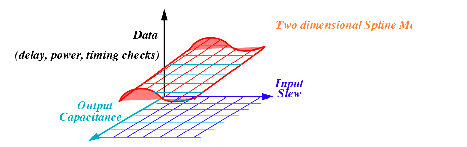
TIMING_model(
timing_arc_name)
Specifies the timing models to use for the particular path in the circuit
Three different models can be used
n
Spline or
Table (one, two or three dimensional)
We are going to use a two dimensional spline model
The two independent axis variables are input slew and output load capacitance
TIMING_model(timing_arc_name) (contd)
(
input_slew_axis value1: value2: ... : value n)
(
load_axis value1: value2: ... : value m)
(data_max
11:data_typ
11:data_min
11, ..., data_max
1m:data_typ
1m:data_min
1m)
(data_max
n1:data_typ
n1:data_min
n1, ..., data_max
nm:data_typ
nm:data_min
nm))))
Similar spline models are used to specify delay and slew for each timing arc
ENERGY_model( ) property is used to specify power for each timing arc
pintype(
input, output, bidir, ground, supply, internal)
Used for output or bidirectional pins. The expression defines the value of the output pin as a function of input pins
Expression syntax is similar to verilog and SDF formats
Describes the input pin condition that must be true for the input pin to drive the output of a tristate cell
load_limit( ), slew_limit( ), capacitance( ), vdrop_limit( )
Other information in this section is required for flip-flops and their equivalent scan cells
scan_equivalent(cell_name)
Slave_clock (clock_condition)
Inverter_output (pin_name)
Value of output when set and reset are both active at the same time
Value of inverted output when set and reset are both active at the same time
Only required for flip-flops, latches and register file cells
Path definitions and Timing Checks
inputPorts (path origin)
=> outputPorts (path end)
Input and output pins for the path
outputTransition (01, 10, 0Z, Z0, 1Z, Z1, 0X, X0, 1X, X1, XZ, ZX)
Name of other pins relevant for timing analysis for this path
Delay model described before to be used for this path
Slew model described before to be used for this path
Path definitions and Timing Checks
(contd)
inputPorts (check_pin) => referencePorts (reference_pin)
Describes the input pin and the reference pin (usually clock) for the check
inputTransition (posedge, negedge, high, low, 01, 10)
Describes the transition for which this check applies
Timing model described before to be used for this check
MPWH (inputPorts(
check_pin) OtherPins(
pin_names) model (
model_name))
Minimum pulse width high timing check
MPWL (inputPorts(
check_pin) OtherPins(
pin_names) model (
model_name))
Minimum pulse width low timing check