Lab 6: BCD-to-decimal decoder and Hexcidecimal-to-Seven-Segment Decoder

2023 - Robucci – removed mux for the sake of moving lab earlier in semester. Mentioned complementary at-home exercise. Added description of seven-segment LED with animations.
Table of Contents
Objective and Overview
In this lab, you will be
- verifying the operation of a BCD-to-decimal decoder (74LS42)
- verifying the operation of a hexadecimal to seven-segment decoder (MC14495)
- learning the operation of a seven-segment LED display
Required Equipment
- 7442: BCD-to-decimal decoder
- MC14495: Hex to Seven Segment Decoder
- Seven-Segment LED Display
- LEDs
- Resisors for current limiting LED current
- DIP Switch (4 switches)
- Resistors 4x 10kΩ (for input pull-up)
Discussion
Input Generation
In this lab the standard Quad DIP switch with pull-up resistors will be used for inputs.
Output Display
First Circuit 10 LED output
For the first circuit, 10 discrete LEDs and 10 current-limiting resistors can be used. The output of the 74LS42 is ACTIVE LOW. There are OVERBARS (e.g. ) on the pin labels in the datasheet to indicate this.
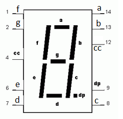
Second Circuit Seven-Segment LED output
For the second circuit, a Seven-Segment LED Display will be used. It has seven primary segments which can be independently activated to display characters. Additionally, this display has a right display point. This display has many LEDs with their cathodes tied together with the intent of a common connection to a low supply terminal. This configuration is called common-cathode.


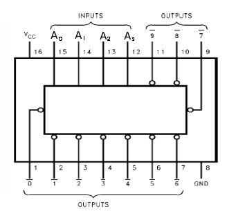
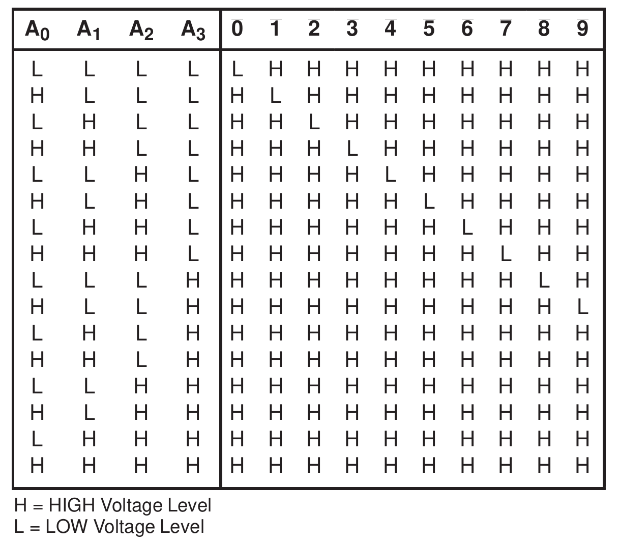
(Circuit 1) BCD Decoder 7442
- “Binary-Coded Decimal” Decoder
- https://www.futurlec.com/74LS/74LS42.shtml
- 4 inputs, 10 outputs
- Input 0000 activates Out 0, input 0001 activates Out 1, etc.
- Active low outputs: the selected output is low, while other outputs are high. This means and LED should be connected in a path from the output to positive power supply terminal, with series current-limiting resistor.
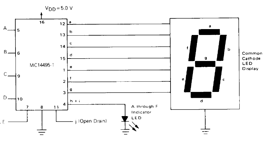
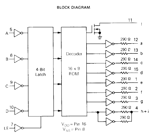
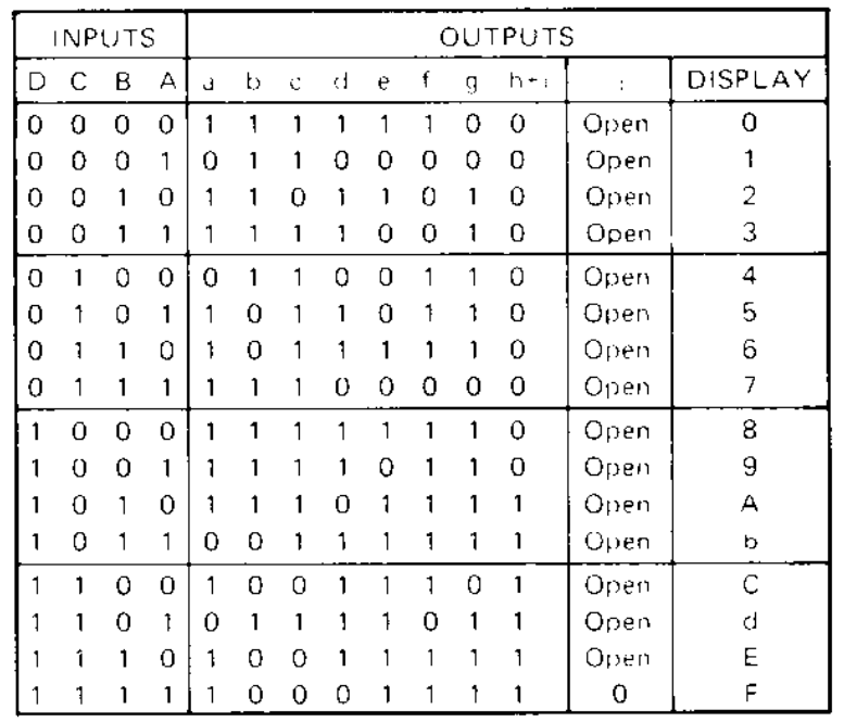
(Circuit 2) Hexadecimal-to-seven segment Latch/Decoder LED Driver (MC14495 IC)
- The MC14495 (https://www.futurlec.com/Motorola/MC14495P1.shtml) can be used to display a hexadecimal character on a seven-segment LED display.
- Inputs A,B,C,D are used to signal a 4-bit value.
- The outputs a-g can be directly connected to a seven segment display.
Current-Limiting Reistors for seven-segment display LEDs
The seven-segment display uses LEDs that you might expect to require the inclusion of current-limiting resistors in a driver circuit. The MC14495P1 has these resistors built-in because it is designed to drive such LEDs. This IC is an example of an integrated circuit with more than digital logic Therefore, you do not have to add current-limiting LEDs to your breadboard.
Prelab
For this lab, the instructor is providing a complementary exercise related to the design of the logic for one of the decoders. That exercise will be turned in as part a lab report, and does not nessisarily need to be completed before lab. Therefore there is no pre-lab submission. Once you complete the lab activity, the exerience may serve as a reference for understanding the logic design goal (i.e. the function of the decoder) for the at-home exercise.
You should otherwise use time before lab to plan your placement and wiring, and/or you may start assembly of your circuit before lab.
In-Lab Exercise
BCD-to-decimal
- Connect the four DIP switch signals to the four inputs A,B,C,D of the 74LS42 BCD decoder.
- Use ten output indicator circuits (resistor and LED) to observe the ten active low-outputs.
- Demonstrate the operation of the circuit to the TA.
📝 TA Verification
Have the TA check and record your completion.Hex to Seven-Segment Decoder
- Without disrupting the previous circuits, connect the four DIP switch signals to the four inputs A,B,C,D of the MC14485 IC.
- Connect MC14485 LE (pin 7) to ground
- Connect MC14485 outputs a-g to appropriate inputs a-g of the seven-segment display.
- Connect the CC (pin 8) of the seven-segment display to ground.
- Demonstrate the operation circuit to the TA. Test input values 0-9, as well as 10-15.
📝 TA Verification
Have the TA check and record your completion.Grading and Submission
50% Completion of In-Lab activity (verified physical circuit demonstration). This lab is grading for completion only, based on demonstration to the TA.
No report is otherwise required for the in-lab activity.
50% At-home exercise on decoder logic design. This is provided by the instructor.