Lab 5: Adders

Table of Contents
Objective and Overview
- In this lab you will learn to build an implemenation of a 1-bit full adder, and use of a multi-bit adder IC 74LS283.
- You will then map the implementation of the 1-bit adder to 74LS ICs gates.
- In this lab you will build and test a 1-bit full adder (Circuit 1), built from basic logic gate ICs. You will then test a provided 4-bit full adder IC (74LS283) (Circuit 2). You will then connect the adders from Circuit 1 and Circuit 2 to create a 5-bit adder (Circuit 3).
Materials
- Quad 2-input AND Gate https://www.futurlec.com/74LS/74LS08.shtml
- Quad 2-input OR Gate https://www.futurlec.com/74LS/74LS32.shtml
- Quad 2-input EXLUSIVE OR Gate https://www.futurlec.com/74LS/74LS86.shtml
- 4-Bit Binary Adder https://www.futurlec.com/74LS/74LS283.shtml
- Three DIP Quad Switch Packages
- Resistors
- LEDs
Theory and Discussion
Examine the following addition operation.

The operation can be described with Boolean logic and Boolean Algebra. A given stage, indexed by k, has the following:
- three inputs: , and carry-in bit
- two outputs: the sum output result bit , and the carry-out bit to the next stage
Switching functions:
- Expressions:
- , i.e. odd parity, an odd number of input bits are 1
- , i.e. at least two input bits are 1
Since binary addition can be described with Boolean Logic, a single stage of the binary addition can be performed with logic gates.
1-Bit full adder
Binary Full Adder:
As an exercise in discussion session, we can verify that the truth table for these expressions matches the desired function for an addition.
4-Bit full adder
A 4-bit full adder, can be constructed from FOUR 1-bit full adders using a carry out bit of each stage as the carry in bit of the next full adder.
Since adders are commonly-used circuits, multi-bit adder ICs are available.
The IO diagram of the 74LS283 is shown below:
The following is a depiction of the 4-Bit full adder annoted with the correspoding pin numbers of the 74LS283:

Numbering starting from 1 vs 0
Note that pin names are numerically offset by 1 from what may be expected (e.g. A1,A2,A3,A4 rather than A0,A1,A2,A3).
5-bit Full Adder
A 5-bit adder can be made from FIVE 1-bit adders, or a 1-bit adder cascaded with a 4-bit adder.
Altogether the circuit is functionally equivalent to the following.
Pre-Lab
Half Adder
The half adder adds two single binary digits A and B. It has two outputs, sum (S) and carry (C). The carry signal represents an overflow into the next digit of a multi-digit addition(https://en.wikipedia.org/wiki/Adder_(electronics).
You can see the truth table of a half adder in the following table:
Inputs, outputs signals are given below:
| Inputs | output | ||
|---|---|---|---|
| A | B | S | Carry |
| 0 | 0 | 0 | 0 |
| 0 | 1 | 1 | 0 |
| 1 | 0 | 1 | 0 |
| 1 | 1 | 0 | 1 |
So you can see from the truth table that the equation for the outputs are as follows:
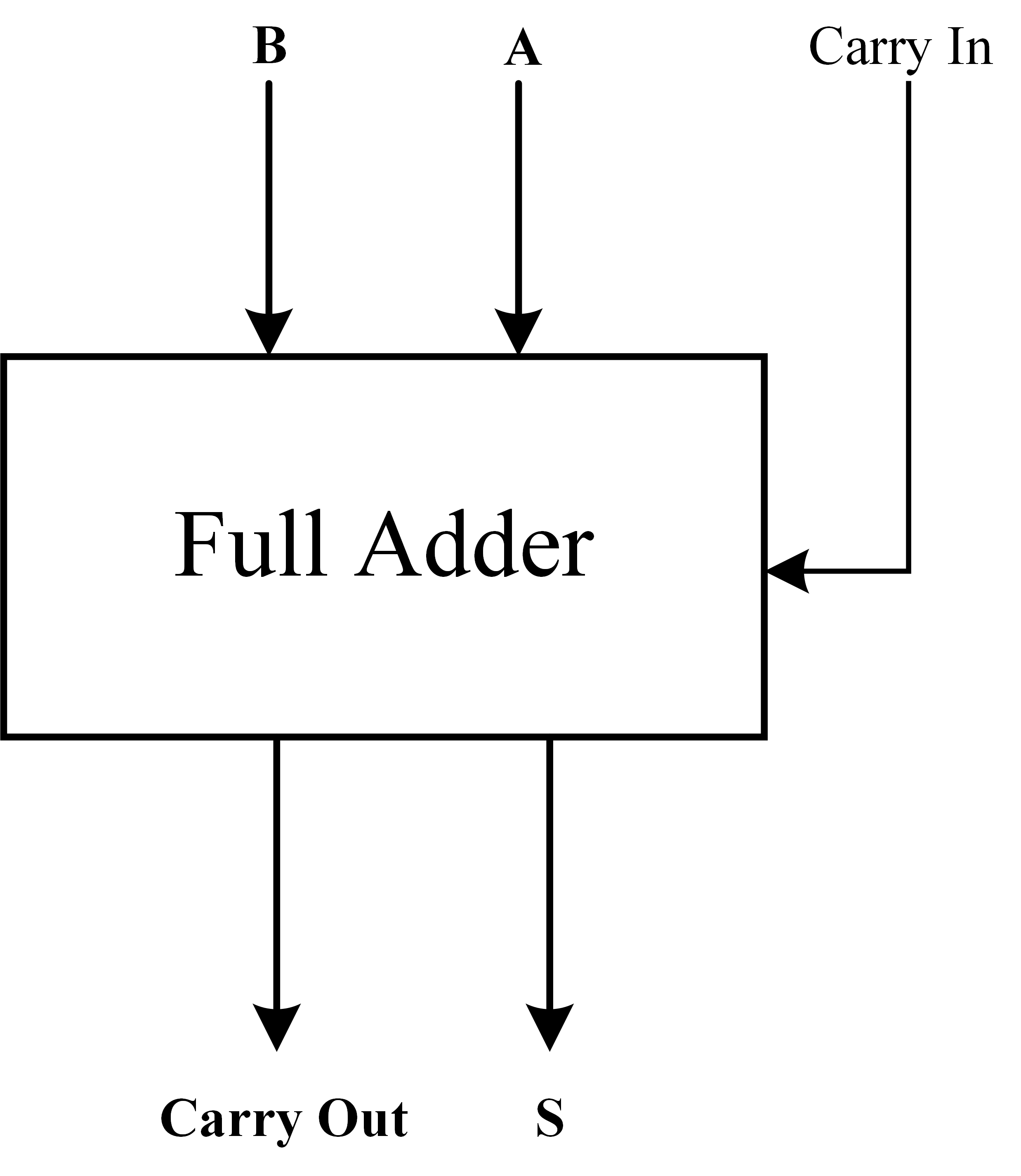
Full Adder
A full adder has three rather than just two inputs: , , and a third input called Carry In. The operation for a full adder is , and the outputs are the same as a half adder,i.e, S and Carry Out.
Required Pre-Lab Exercise
Complete the truth table of a 1-bit full adder
| A | B | Carry In | Sum | Carry Out |
|---|---|---|---|---|
| 0 | 0 | 0 | _ | _ |
| 0 | 0 | 1 | _ | _ |
| 0 | 1 | 0 | _ | _ |
| 0 | 1 | 1 | _ | _ |
| 1 | 0 | 0 | _ | _ |
| 1 | 0 | 1 | _ | _ |
| 1 | 1 | 0 | _ | _ |
| 1 | 1 | 1 | _ | _ |
Challenge Exercise (not required/graded)
Suppose you have two half adders, find a way to create a full adder using two half adders. Please draw the block digram and logical gate-level circuit of your design. In lab you will learn to use a full-adder instead.
![]()
Plan Circuit and Construction Ahead of Time
You should attempt to create a diagram of your circuits before you come to lab. Preparation is your responsibility, but it is not a graded component.
Lab Exercise
- Build and test a 1-bit Full Adder, built from several 74LS series ICs. It should be built and tested on the breadboard. Leave room for the IC74LS283.
TA Verification for 1-bit adder: _________________________________________
-
Leaving the 1-bit adder circuit intact on circuit on the board, place and test the IC74LS283. You should test the carry input and carry output bits. Use the test examples provided, which you used in your testbench, from the previous lab.
A B Carry In Sum Carry Out 0000 0000 0 _ _ 1011 0100 0 _ _ 1010 0110 1 _ _ 1000 0101 1 _ _ 1111 1110 0 _ _ 1111 1111 0 _ _ 1111 1110 1 _ _ 1111 1111 1 _ _
TA Verification 4-bit adder: _________________________________________
- Connect the 1-bit adder to the 4-bit adder to create a 5-bit adder. Modify each of the 8 example input tests from last time as appropriate to test a 5-bit adder.
Record your results and have the TA Verify the operation of the 5-bit adder.
TA Verification 5-bit adder: _________________________________________
Be sure to read the Lab Report and Grading Section to understand what should be saved and collected during the lab.
Lab Report and Grading
- The prelab will be worth 10%
- TA Verification of Completion of Part 1 in lab will be worth 20%
- TA Verification of Completion of Part 2 in lab will be worth 20%
- TA Verification of Completion of Part 3 in lab will be worth 20%
- The lab report will be worth 30%
- Be sure to include schematics/drawings and truth tables for the three circuits.