Lab 11: State Machine Design and Implementation

Statemachine design discussion and exercise design provided primarily by Dr. Phatak
Lab design, documentation, and considerations provided by Dr. Robucci
Table of Contents
Objective and Overview
In this lab, you will be designing a Finite State Machine (FSM). Based on the truth table of the states you will be able to design a circuit with Flop Flops such as DFF, JK-FF, and T-FF.
Discussion and Theory
Mealy and Moore FSM
Mealy machines and Moore machines are two types of FSMs. If the output of FSM depends on both the present state and the present inputs of the FSM it must be a Mealy machine. However, if the output depends on just the present state, it is a Moore machine.
A state diagram is depicted as a directed graph with nodes representing states and edges/arrows representing every possible transitions (including the “state in the same state” transition). When designing a finite state machine, for every state carefully consider every possible input combination.
If the desired behavior is to stay in the same state, include a graph arrow going out and looping back into the state. One may note that for more complex systems with many input bits, it is common that for many states the desired behavior for almost all possible inputs is to stay in the same state and for only a few input cases leaving the state is desired. So as to avoid clutter in depiction of Moore machines, one might choose to only draw edges for transitions out of the state and provide a note in the state diagram that the default behavior if an input cases is not covered in a any given state is to stay in the same state. However, this uncluttering is advised against for students learning digital design. It is important to get into a strong habit: for EVERY state, you must explicitly consider EVERY possible input vector (an input vector is just a term for an ordered list of input values). This is reinforced by making sure that for all states, every possible input case is covered, which sometimes means drawing a lot of “loops” (edges with the same state as the source and destination) to communicate that all input cases have been explicitly considered.
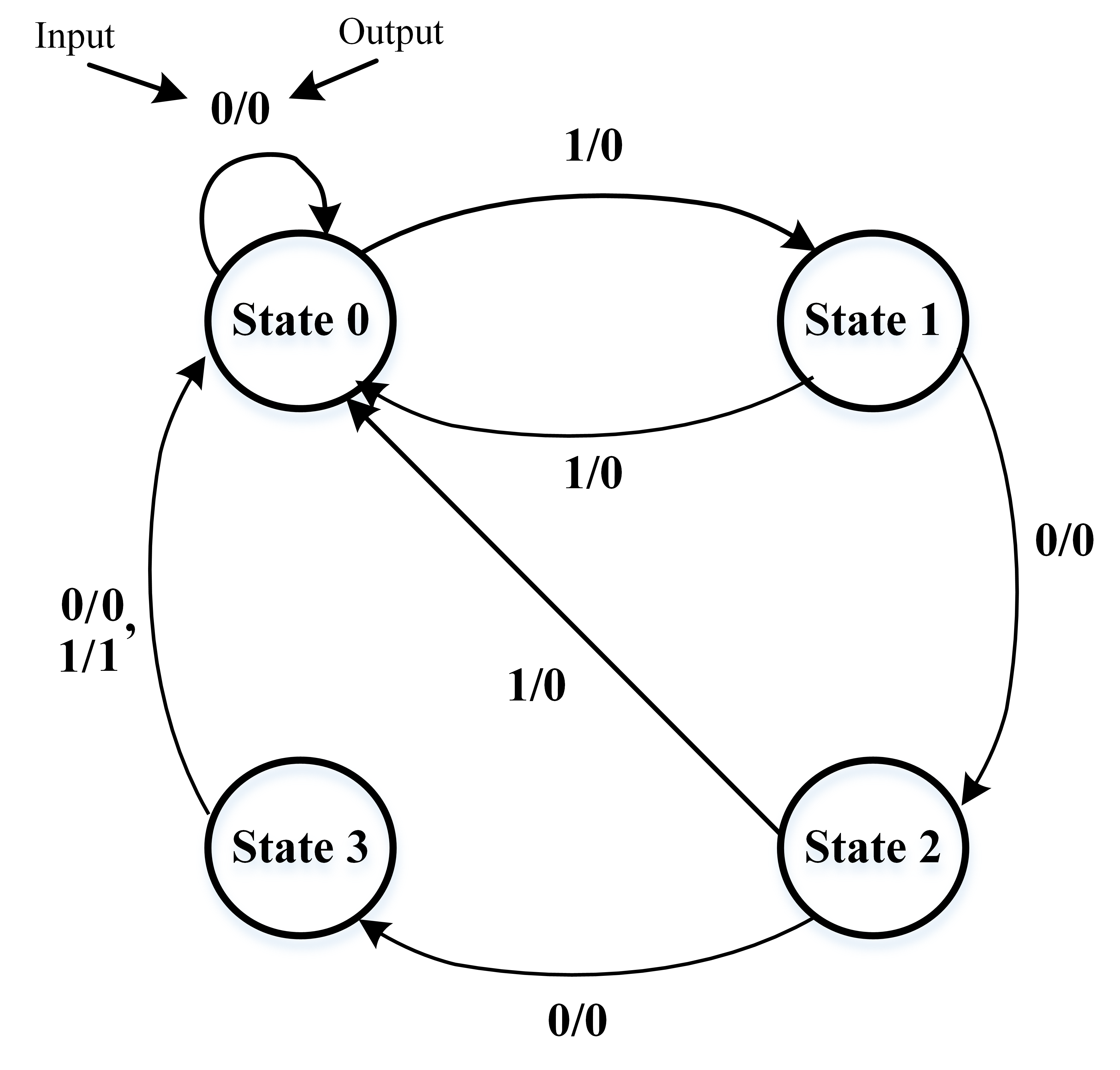
We will discuss an FSM to detect the input token sequence 1001, and then implement the sequence detector with combinational logic and a DFF. We call the sequence 1001 (which is to be recognized) as the “token” sequence (sequence of tokens).
The design is based on a Mealy design, as evidenced by the current output’s dependance on the current input.
The interpretation of the label “state k” inside the circle
representing state k is "the ckt/machine is in state k (or in other words,
it reaches state k if it has seen k bits of the N-bit token in the previous k clock cycles.
In other words “the number of bits of the token seen thus far” is a “state-descriptor” that is the optimal choice of a state descriptor
for this problem.
In general the steps in the synthesis of a sequential system are as follows
- word description
- state-descriptor selection
- expressing the operation as a state transition diagram or
equivalently as a state transition table - minimization of the state table leaving the states as symbols
- state-assignment (i.e. assign a label of binary bits to each state)
- boolean truth table
- logic level/boolean minimization (via K maps or Quine McClusky)
- once you have the boolean expressions, implement it using gates.
Step (2) is the hardest: it is an art not a science.
in other words, there is no cook-book recipe that tells one how to come up with the optimal state descriptor. it is “black magic”…
no, i mean it requires lot of practice. thats the only way to acquire that skill. (young jedis must work hard and focus if they want the control the force).
Unfortunately the selection of state descriptor can have devastating consequence that ripple all the way thru the remaining steps of the design. if your state descriptor is not sufficiently expressive/powerful, your state diagram can become unnecessarily complicated.
I hope you get a chance to first-hand experience/see examples wherein choosing the most immediately obvious state descriptor leads to a state transition diagram that is a 2-D graph; but crafting the correct state descriptor collapses that complicated 2-D state diagram into a 1-D linear structure. (I encountered this for the first time in my graduate course in UMASS CS way back in 1989, on queueing theory; taught straight out of Kleinroc’s classic textbook “Queuing Systems Vol I”. if you choose the correct state descriptor, your life becomes bearable otherwise you can never solve the problem. I deliberately include the elevator control problem in the lecture viewgraphs to illustrate the importance of selecting the correct state descriptor).
Step 3. is tedious but straightforward once a state descriptor is selected.
Step 4 (state table minimization) requires an entire new framework of “compatibility graphs” but is
fairly straightforward.
step 5 state-assignment problem: it is NP-hard (whatever that means, don’t worry too much about P vs NP issues right now… just rote memorize for now that the state assignment problem is NP-hard which essentially means that finding the optimal assignment of labels to states requires super-polynomial (exponential) effort. Worse yet even if someone goes thru all that effort and finds the optimal assignment and tells you the answer; if you want to verify that it is indeed the best possible solution; you have to do exponential amount of work even to verify optimality of the solution).
steps 6,7,8 are straightforward. you guys are champions of k-maps and QM methods and should be able to get up from sleep and "shout De-Morgan’s theorems in reverse to scare away a wild-bear if you run into one…(just joking ).
are you aware that logic minimization is an NP hard problem ??
Boolean SAT (satisfiability) is itself NP; finding the minimal cover is NP hard…
Example Design
In this section we are going to design a FSM to detect the input sequence 1001 in the previous figure, and then implement the sequence detector with DFF. We call the sequence 1001 (which is to be recognized) as the “token”.
The design is based on a Mealy design, as evidenced by the current output’s dependance on the current input.
Step A
First, we need to draw the state diagram of question.
Step B
Then, we should draw the state-transition table.
| Present State | New State / Output | |
|---|---|---|
| if input is 0 | if input is 1 | |
| State 0 | State 0 / 0 | State 1 / 0 |
| State 1 | State 2 / 0 | State 0 / 0 |
| State 2 | State 3 / 0 | State 0 / 0 |
| State 3 | State 0 / 0 | State 0 / 1 |
Step C
Now, for designing circuit, we need assign a number to each state. There are various methods to assign number to states such as binary, gray, and one hot code. In this lab we use binary code as we assign each state a number which starts from 0 for the first state and N-1 for the state N.
| State Name | State Assignment |
|---|---|
| State 0 | 00 |
| State 1 | 01 |
| State 2 | 10 |
| State 3 | 11 |
Please note that the total bit number for your FSM state is , where N represents the number of states. This is the number of Flip Flops required in the circuit implementation of the FSM.
Step D
To design the circuit, we should redraw state-transition table base on the assigned state that we did in the Step 3. This table is completed by considering the Flip Flop excitation-response behaviors as shown in the following tables for DFF, TFF, and JKFF.
-
DFF
Desired State Behavior Required Input Present State Next State D 0 0 0 0 1 1 1 0 0 1 1 1 -
TFF
Desired State Behavior Required Input Present State Next State T 0 0 0 0 1 1 1 0 1 1 1 0 -
JK-FF
Desired State Behavior Required Input Present State Next State J K 0 0 0 X 0 1 1 X 1 0 X 1 1 1 X 0
Accounting for a 2-bit internal state and a 1-bit input, there are eight cases to cover in this design. The desired next state and out depend on the desired state diagram you want to implement. The inputs of the flip-flop are then designed based the type of flip-flop used for a given bit in the state. While one could use a different flipflop for every state bit, at least be able to consider a design using only one type of FF.
| Possible Cases | Desired | Required Input for Flip-Flop | |||||||
|---|---|---|---|---|---|---|---|---|---|
| Present State | Input | Next State | Output | DFF | TFF | JKFF | |||
| X | Z | ||||||||
| 00 | 0 | 00 | 0 | 0 | 0 | 0 | 0 | 0X | 0X |
| 00 | 1 | 01 | 0 | 0 | 1 | 0 | 1 | 0X | 1X |
| 01 | 0 | 10 | 0 | 1 | 0 | 1 | 1 | 1X | X1 |
| 01 | 1 | 00 | 0 | 0 | 0 | 0 | 1 | 0X | X1 |
| 10 | 0 | 11 | 0 | 1 | 1 | 0 | 1 | X0 | 1X |
| 10 | 1 | 00 | 0 | 0 | 0 | 1 | 0 | X1 | 0X |
| 11 | 0 | 00 | 0 | 0 | 0 | 1 | 1 | X1 | X1 |
| 11 | 1 | 00 | 1 | 0 | 0 | 1 | 1 | X1 | X1 |
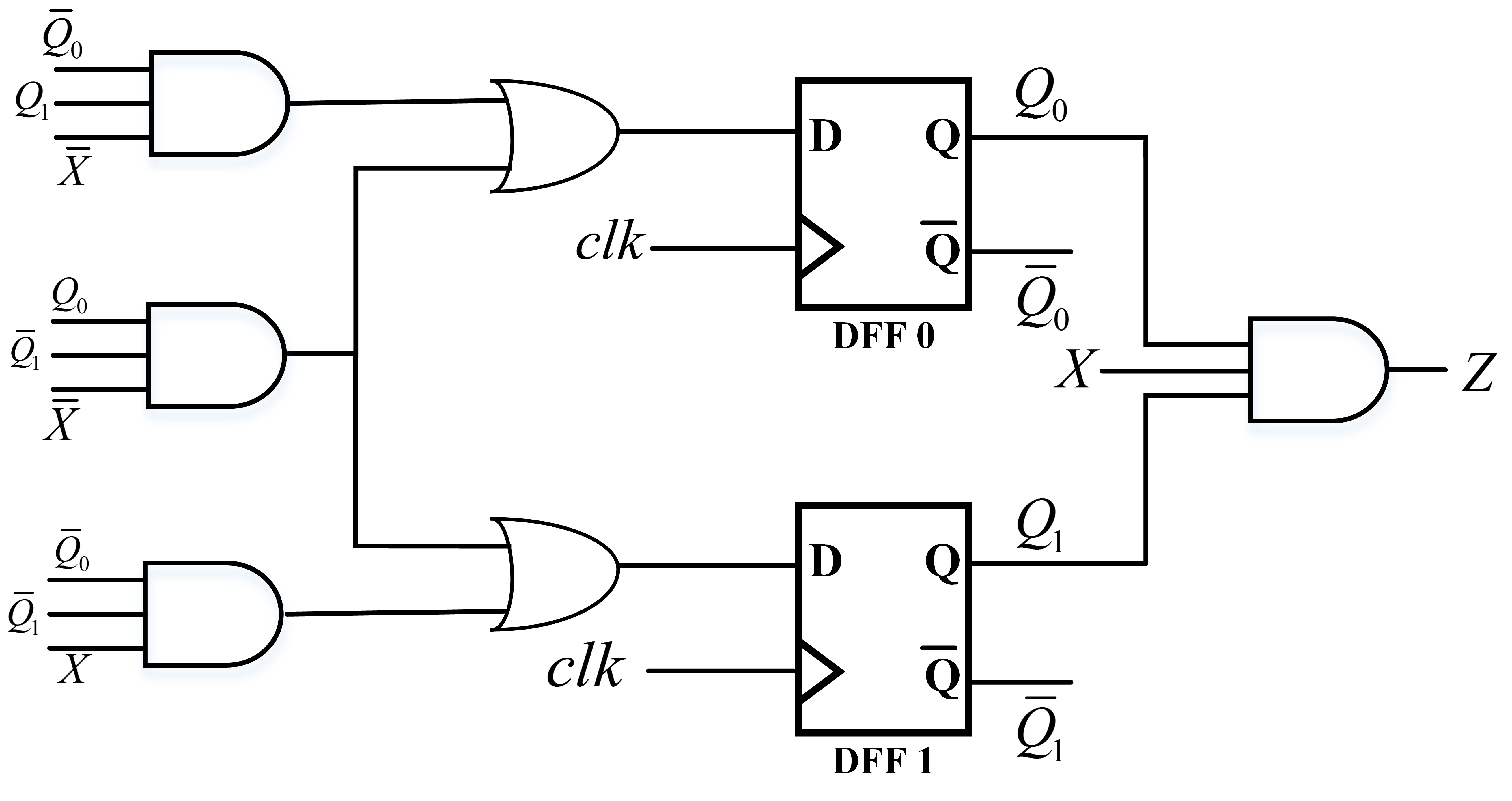
Step E
Finally, to implement the circuit, we should find the switching expression for outputs, input of Flip Flops based on the value of present state and the inputs through the Karnaugh map. If the FSM is designed by DFF:
Prelab
- Modify the sequence detector in the Lab discussion section in a way that could detect the overlap sequence. That means if the input sequence is 1001001 the FSM should detect 1001 twice. This FSM should be designed in Moore machine style. (Do you think you can design the FSM just by 4 states?)
- Draw the state transition table of your Moor machine by considering TFF in your table.
- Design the circuit of your Moore FSM with TFF.
Lab Exercise
In this lab, you will be designing a Mealy finite state machine (FSM) that will detect an overlapping sequence of 11001 in the input.
- Draw the state diagram of sequence detector
- Draw the state transition of your FSM using DFF
- Design the circuit of your FSM with DFF.
Lab Report and Grading
- The prelab will be worth 20%
- Lab Exercise 60% (completion based this semester, should be observable by the lab report)
- State Diagram of FSM.
- State Transition of FSM.
- Implementation of FSM circuit with DFF
- Lab Report (20%)