Lab 1: Introduction to the lab equipment: Multimeter, Power Supply,Resistors, and Breadboard
Created by: E.F.C. LaBerge based on presentation material from T. Kuester July 2013
Updated
E. F. C. LaBerge and Aksel Thomas January 2017
Ryan W. Robucci and Maloy Kumar Devnath August 2021
Ryan W. Robucci no change to assignment, reallocated part of lab report to be pre-lab August 2022
The purpose of this first lab exercise for CMPE212 is to introduce the student to some basic equipment and instrumentation that will be used throughout the semester. In this initial lab, photographs are frequently used to help students make the proper adjustments. While this graphic-intensive approach will occasionally be used in later lab descriptions, students will eventually be expected to proceed from written material, formulas, and circuit descriptions alone, without the explicit visual instructions provided by the photos.
This week we will learn to use and protect the multimeter, the power supply, and the basic breadboard, while also picking up the skill to read resistor codes.
By the end of this lab exercise, you should be able to do the following:
Read a resistor code.
Use a multimeter to measure resistance.
Use the Agilent power supply.
Use a multimeter to measure voltage.
Use a multimeter to measure current while avoiding damage to the multimeter.
Build a circuit on a breadboard.
Measure current and voltage within a breadboard circuit.
Equipment
You will require the following equipment for this lab:
Agilent E3631A Triple Output Power supply (at your lab station)
Extech digital multimeter, obtained from the TA.
Multimeter probe cables, one black, one red. These hang on a labeled rack at the end of the lab.
The breadboard, obtained from the TA.
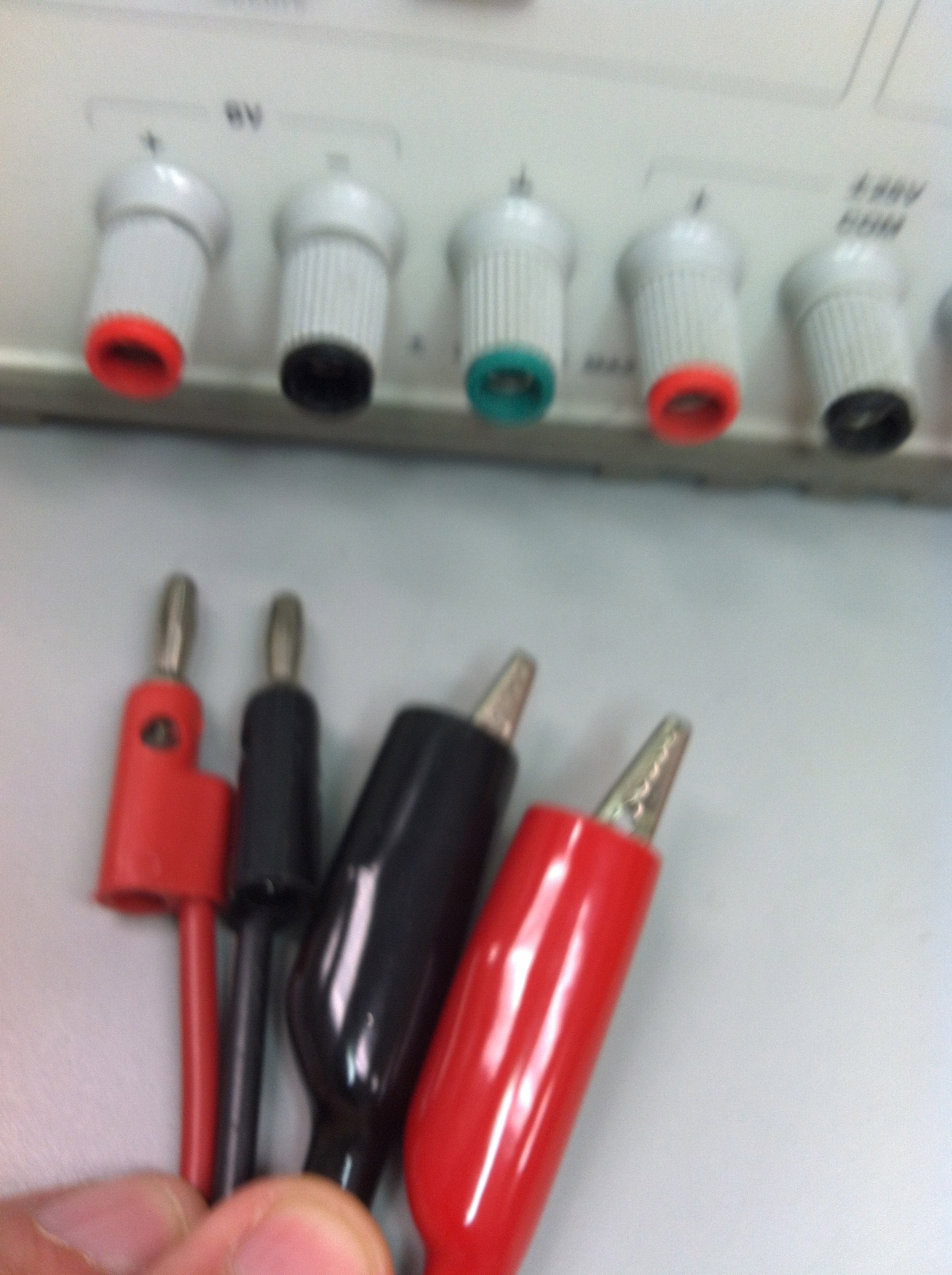
Banana-to-alligator power supply/signal cables, one black, one red These hang on a labeled rack at the end of the lab.
Your lab kit, obtained from the TA.
General Lab Procedures
No food or drink in the lab. The equipment is expensive and we have no spares, so an untimely spill could really impact students in many different courses.
Neatness is the key to lab success! If you don’t keep your workspace and your breadboard circuit as neat as possible, you will either ruin some necessary element of the experiment or take an unacceptably long time to complete the lab. Get in the habit of keeping things tidy as you go along. In particular do not (!) let cables drop on the floor, where they can be rolled over and destroyed.
At the end of class, you are responsible for returning all cables back to the racks, for repacking your lab kit, and for cleaning up your lab station area.
Report all broken or malfunctioning equipment to the TA as soon as you notice it.
ENGAGE your brain so that you don’t accidentally destroy or damage something. Accidents happen, and we will inevitably lose some multimeter fuses. Inform the TA at once if something bad happens. And then learn from your mistake and don’t repeat the action that caused the problem.
For this lab, there is no pre-lab or lab report to turn in. Your lab grade for this session will be based solely on your registered attendance, so make sure that the TA knows your are here.
Pre-Lab Assignments
Information about pre-labs will be included in the lab document each week, and will need to be submitted by 9:00 AM Friday unless posted otherwise. This semester we plan to use Blackboard for submission of Pre-Lab Assignments. Your instructor will provide you information and guidance on this task.
For this initial week, we will not require a separate pre-lab submission or check it before lab. This week only, submit your pre-lab exercises only as part of your lab report. This is your pre-lab exercise:
Write a brief description of your previous experience if any with electronics hardware and labs, including any physics lab experience. Mention the test and measurement equipment that you used. Mention electronics components used.
Create a drawing of the circuit that you will build and measure in-lab. If you have any questions you may reach out to the TA in advance of the Friday lab.
Procedure for today
Multimeter as an ohm meter
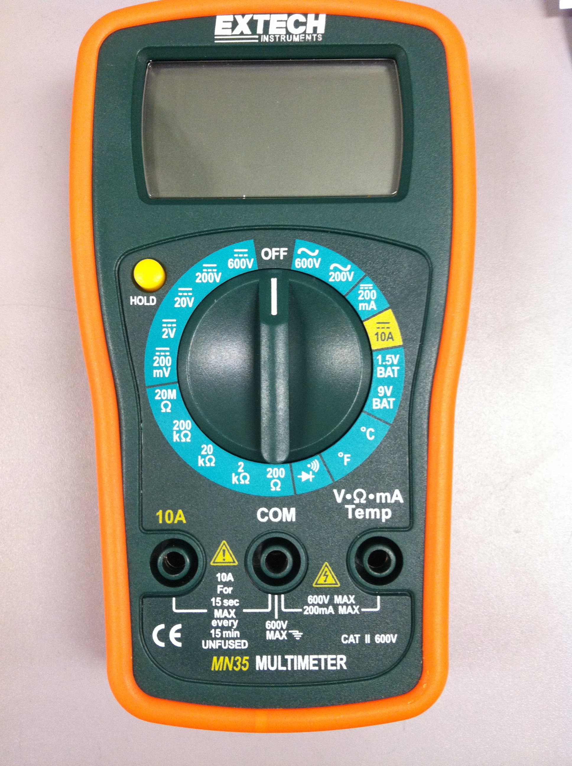
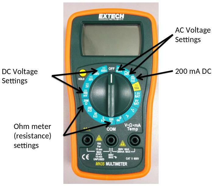
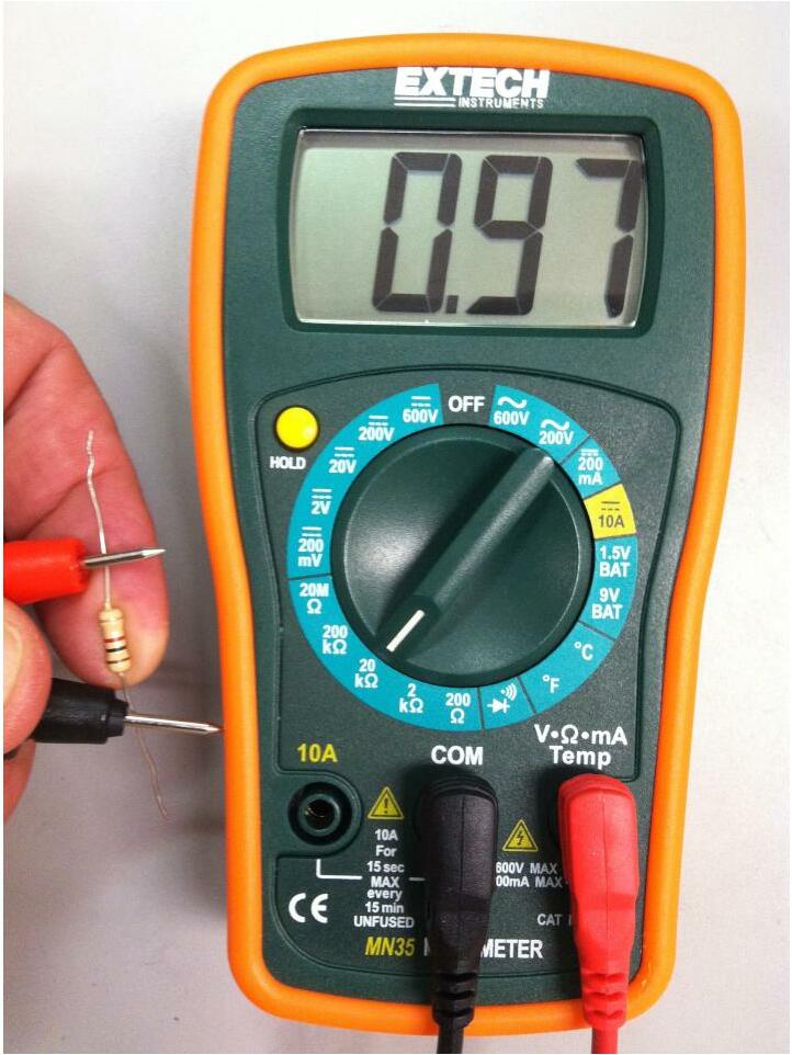
The digital multimeter, shown in Figure 1, is a device that enables you to measure circuit parameters directly. With care, it is capable of a large range of measurements. Without care, it becomes a useless lump of electronics in a plastic case.
Basic Extech Multimeter
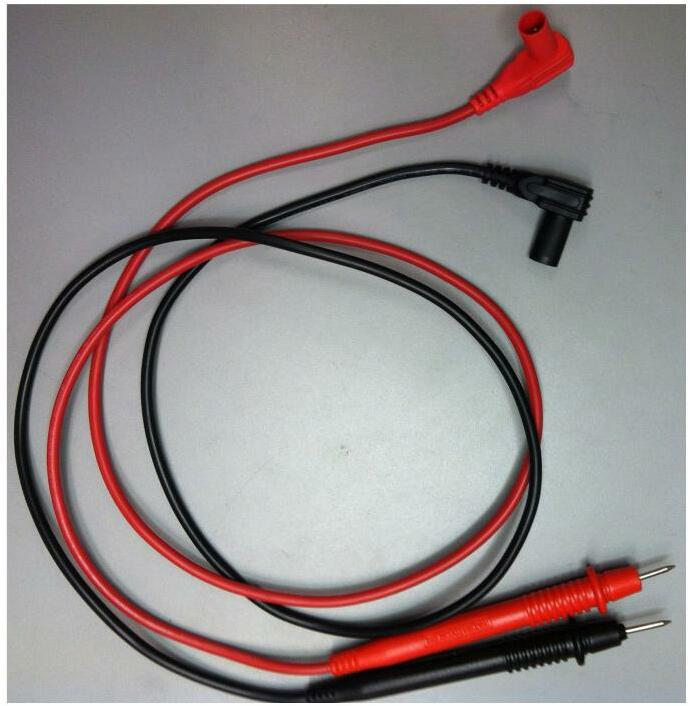
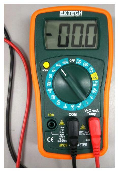
To use the multimeter you first connect the cables as shown in Figure 2. The choice of red for “positive” or and black for common is the usual convention. The meter will work correctly no matter which color you use, but you will almost certainly get confused if you don’t connect the leads as shown in Figure 2.
Extech Multimeter with Leads Connected in Standard Way
The multimeter is so named because it can make a multitude of measurements, depending where the selector dial is set. There are ranges of settings for DC voltage measurements, AC voltage measurements, DC current measurement, and resistance measurement, as identified in Figure 1.
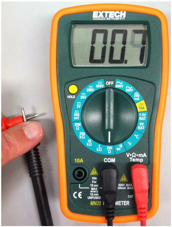
With the selector dial set to , touch the ends of the probes together. As we will see, a connection of two wires has a resistance of , so the display should show 00.0, or something close, maybe a few tenths of an ohm, which may flicker around. Figure 3 shows a typical output. Question: What are possible causes for the measurement not being steady at zero ohms? Talk about this with your lab partner.
First Multimeter Task
Now repeat the simple task with other resistance settings. What do you see and why? Do the fluctuations go away? Discuss this with your lab partner. Note that the resistance range setting determines the maximum resistance that can be measured on that setting. Attempts to measure a higher resistance will not harm the meter, but will result in a display that shows the numeral “1” in its leftmost digit with no additional significant figures. To get a measurement, select a higher range of resistance.
Reading Resistors
Which brings us to the subject of resistors. As noted in class CMPE212 will use three different types of passive electrical components: resistors, capacitors and inductors. Your lab kit contains examples of all three, but we’ll worry about resistors first.
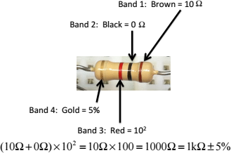
Decoding a 1kΩ Resistor Figure 4 illustrates a typical resistor. All simple resistors, like this one have two leads extending from a nearly cylindrical body.
The value of the resistor, in ohms, is given by the colored bands. There are four such bands on each resistor, with three being closely grouped and one band near the opposite end of the resistor. Each color corresponds to a single decimal digit, with the mapping indicated by Table 2.
The bands are decoded in the following way:
Band 1 is the 10’s digit. In Figure 4, Band 1 is brown, corresponding to a value of 10.
Band 2 is the 1’s digit. In Figure 4, Band 2 is black, corresponding to a value of 0.
Band 3 is the multiplier, indicating the power of 10 used to multiply the sum, (Band 1 + Band 2). In Figure 4, Band 3 is red, corresponding to a value of 2.
Table Standard Resistor Color Code with Mnemonic
Band Color
Mnemonic Value
Decimal
Black
Better
0
Brown
Be
1
Red
Right
2
Orange
Or
3
Yellow
Your
4
Green
Great
5
Blue
Big
6
Violet
Venture
7
Grey
Goes
8
White
West
9
Therefore, the value of the resistor shown in Figure 4 is 1kΩ. All of the resistors in your lab packet can be identified in this way.
Find the resistor in your packet and measure it with your multimeter. Which setting should you use? Will the setting work? Select and measure five other resistors from your kit, identifying the value first by the color code and then checking to see if you correctly decoded the value by measurement with the multimeter. Be sure to select the correct range for the measurement.
Measurement of 1kΩ Resistor
Figure 5 shows the measurement of the resistor. The measured value is 970Ω . What’s wrong? It turns out that nothing is wrong! The fourth band is used to indicate the precision of the resistor value, and uses a different color code, as shown in Figure 4. All of your resistors have gold bands, indicating a precision of 5%. Five percent of 1k is 50, so the actual value of our resistor will vary between 950Ω and 1050Ω. The measurement shown by Figure 5 falls within this range.
Table Standard Resistor Precision Code
Band Color
Precision
Brown
1%
Red
2%
Gold
5%
Silver
10%
Finally, note that it makes no difference whatsoever which way you do the measurement. That is, the red lead may be at the brown band end or at the gold band end. The value of the resistance is the same.
It is expected that after finishing the section, we can understand the resistor color code and measure it. The measured resistor’s value will be in range.
The Value of a Resistor from the Color Table
The DC Power Supply
Each lab position is equipped with a computer, a Tektronix arbitrary signal generator, a Tektronix oscilloscope, and an Agilent triple-output Direct Current (DC) power supply. As discussed in class, DC means that the current (and voltage) remain essentially constant over time. In particular, the voltage (and current) do not vary sinusoidally with time.
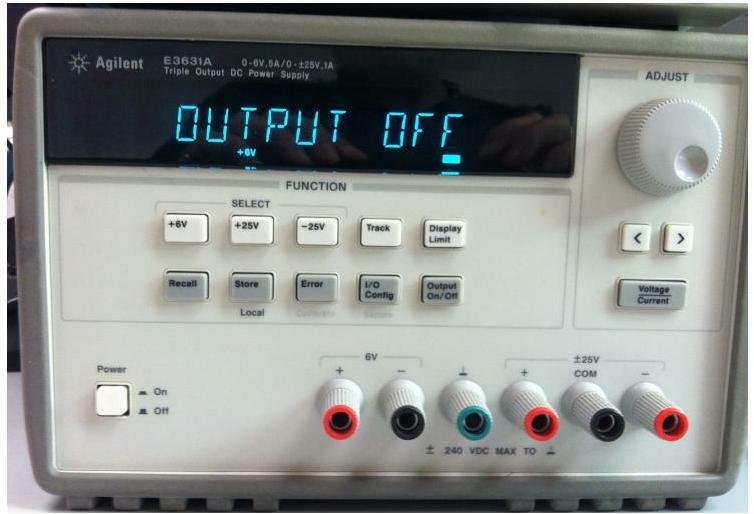
As noted in class, all linear circuits need some source of energy, that is, some independent voltage or current source. In this lab, our energy source will frequently be the Agilent power supply, shown in Figure 6. Turn the supply on by pressing the Power ON/OFF button on the lower left. You will see the display as indicated in Figure 6. The Agilent unit provides a +6V supply, a +25V supply, and a supply. For today, we will only use the 6V supply. The other are controlled using the same steps we will practice today.
Agilent Triple Output Power Supply
The outputs are provided from the six output plugs along the lower right side of the Agilent unit. For today, we’ll only need the two plugs on the left hand side, indicated 6V “+” and “”. As with the multimeter, the convention is to use a red connection in the red (or plus) plug and a black cord (or a “not red” cord) in the black (or minus) plug.
To set the supply, we have two decisions to make: 1) do I want this to be a voltage source or a current source, and, 2) which supply source do I want. For this lab, we’ll use +6V voltage source. With the unit turned on, but no cables connected, press the grey “Output On/Off” button on the right end of the second row of buttons in the Function area. Then press the white +6V button on the left end of the first row of buttons. The +6V indicator will show up (under the middle zero in the decimal voltage readout), and 0.000V and 0.000A (or thereabouts) will be shown in the display.
To set the power supply, use the following procedure.
Locate the Adjust knob in the upper right and press the Voltage/Current button until one of the digits in the voltage display is blinking.
Use the left ( < )and right ( > ) cursor buttons in the Adjust section until the “ones” digit is blinking. Adjust the ones value to “3”,
Then use the right cursor button to move the blinking digit to the “tenths” position and adjust that value to be 3.
Continue to adjust the voltage to be 3.300 volts using the cursor and adjust knob as necessary. Don’t worry if the least significant digit (millivolts) fluctuates by a couple of units.
After following these four steps, the voltage between the plus and minus terminals of the 6V output should be 3.3V.
We will now use the multimeter to measure this voltage.
The multimeter as a voltmeter
Follow these steps to use the multimeter to measure the voltage at the
output of the power supply.
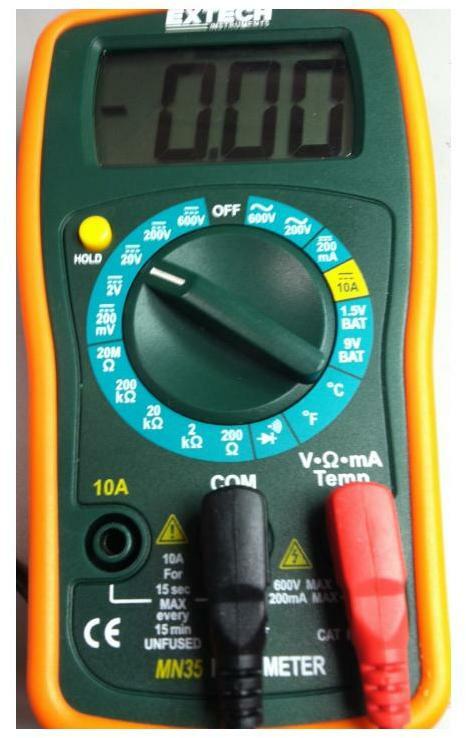
Set the multimeter to the 20V (DC) setting, as indicated in
Figure 7.
Multimeter Set for 20VDC Scale
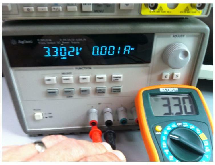
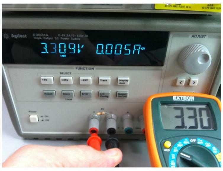
Carefully (!) touch the probe ends to the red (plus) and black (minus) terminals of the 6V output of the supply, as shown in Figure 8. The multimeter should read 3.30V, as shown in the figure.
Measuring the Agilent Output Voltage
Turn the Agilent supply voltage off with the Output On/Off button. Leave the output off while completing this step. You should always turn the output off when adjusting your circuit! Unscrew the ends of the red and black 6V terminals to expose two small holes in the terminals. Bend the leads of a resistor to match the distance between the holes. Then insert the resistor and once again tighten the obs.
We’re going to turn the output on. What will happen? Once you have answered, the supply voltage back on and use the multimeter in the same manner as before to measure the voltage between the red and black terminals of the Agilent 6V output, as shown in Figure 9. Note the value of the current display on the Agilent. Using Ohm’s Law, does your instrument display the right answer? Does the instrument in Figure 9 display the right answer? How can we determine the right answer? Before we find out, TURN YOUR OUTPUT OFF using the Output ON/OFF button!
Figure Measuring Output Voltage Across 1kΩ Load
The multimeter as a ammeter (used to measure current)
CAUTION:
If the multimeter is used incorrectly to measure current, you WILL (no doubt about it) burn a fuse and render your meter inactive. There is only ONE safe (i.e., non-destructive) way to measure current. This method is described in the following steps. Follow this method EVERY time you measure current.
Before we start, here’s the explanation of why it has to be done this way. When the multimeter operates in one of the voltmeter modes (used in Section 4.4, above), it is configured as a high-resistance device. By following the procedure in Section 4.4, we always measure voltage with the meter in parallel with the circuit element(s) across which we wish to determine the voltage. So in Figure 9, the multimeter (in 20V mode) is connected between the same two terminals (red and black 6V) as the resistor. When two elements (the resistor and the multimeter) are connected in parallel they have the same voltage across them. Because the multimeter in voltage mode is a high resistance device, very little current flows through the multimeter. All is well.
But when the multimeter operates in one of the ammeter modes, it is configured as a low resistance device. If you connect the low resistance device in parallel, as in Figure 9 a large amount of current will flow through the meter, potentially destroying it.
NEVER, NEVER, NEVER connect a multimeter in ammeter mode in parallel with any circuit element. Never. Really. Never.
Current must always be measured in series, using the following steps or their equivalent. When two elements, say the multimeter and a resistor, are connected in series, the same current flows through both. So the only way to measure the current through a given element is to connect the multimeter in series with that element.
With these warnings, measure the current in the resistor using the following procedure.
Make sure the Agilent output is off, as indicated by the display message “Output Off”.
Unscrew the red terminal and remove the end of the resistor from the red side. Leave the black side of the resistor connected. Bend the resistor so it is stands up from the black terminal. Re-tighten the red side terminal (without the resistor!).
Turn the Agilent output on.
Set the multimeter to the 200mA setting.
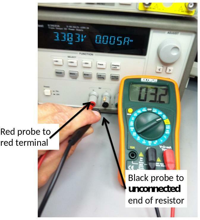
Touch the black probe from the multimeter to the unconnected end of the resistor. Do NOT touch the black terminal of the Agilent or you will blow the fuse in the multimeter! Touch the red probe from the multimeter to the red terminal of the Agilent. Your multimeter should read 3.2-3.4 mA, as shown in Figure 10.
Adjust the Agilent output voltage (see Section 4.3, above) to 5V and repeat the measurement. What is the theoretical answer for the measured current through the resistor?
Turn the Agilent output off. Unscrew the black terminal and remove the resistor.
Measuring Current in the 1kΩ Resistor
The Breadboard
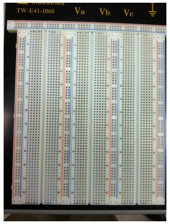
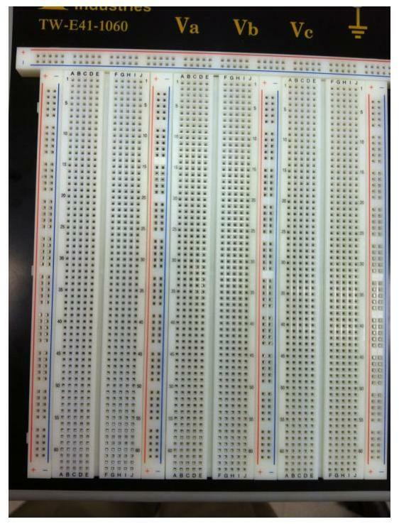
Throughout the CMPE212 lab experience, we will be building and testing circuits that combine various elements. The platform on which we will build these circuits is the breadboard, shown in Figure 11, with an expanded view in Figure 12. The breadboard consists of rows and column of tiny sockets. To build up our circuits, we will plug the elements into appropriate sockets and then connect the elements with wires from our lab kits. Successful construction of the circuits needs an understanding of the organization of the rows and columns of the breadboard.
Breadboard
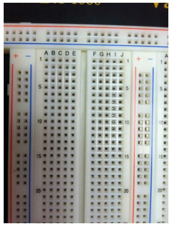
In Figure 12, we see, on the far left and to the right of column J, an indication of “+” with a red line that parallels the entire column of sockets. All of the sockets in the column are connected together. If we put a voltage on any single pin in that column, the same voltage applies at all other pins in the “+” column. This is true wherever we see the red “+” and the red line. Your breadboard may include such an indication across the top or bottom as well as in several vertical columns.
Note that only sockets in the individual “+” columns or “+” rows are connected. The separate “+” columns and rows are not connected to each other, unless you do so with a separate wire.
The same convention holds for the columns (rows) indicated with a blue “” and a blue line. Typically, we will use these “+” and “” connections to provide voltage to our breadboard circuit. We’ll see an example of this shortly.
Still referring to Figure 12, turn your attention to the two parallel matrices of sockets, organized into two sets of rows and columns. Every fifth row is identified by a number (1, 5, 10, etc.) and every column is labeled with a letter (A,B,…,E and F,G,…,J). In this section of the breadboard, the rows are not connected to each other. In any particular row, sockets A-E are connected to each other, and sockets F-J are connected to each other, but A-E are not connected to F-J, unless you make that connection externally.
Breadboard, Expanded ViewBreadboard, Connectivity
Pulling it all together
We will now combine the procedures we have learned to build and test the simple circuit shown in Figure 14. To build this circuit, we need the breadboard, two resistors, assorted wires from your lab kit, and two banana-alligator plugs from the racks in the back of the lab. We will use the Agilent power supply to provide the 5V independent voltage source.
Simple Test Circuit
Construct and test the circuit using the following procedure.
Select a red wire from your pack and insert one end into the upper-left socket of the “+” column on your breadboard. Select a blue or black wire and insert on end into any socket of the “” column about 5 cm below the red wire.
Select a short (~1 cm) wire of any color. Insert one end into the “+” column near the upper left socket. Insert the other end into row 3, column C.
Select a resistor, bend its leads appropriately. Insert one lead into row 3, column D. Insert the other lead into row 3 column G.
Select a short (~1 cm) wire of any color. Insert one end into row 3, column J. Insert the other in row 7 column I.
Select a second resistor and insert one lead in row 7 column J and the other in row 12 column J (or there about.)
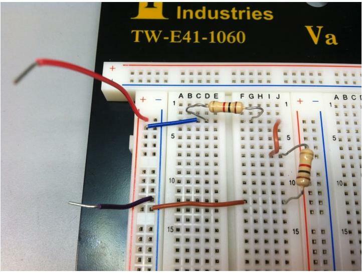
Select an appropriate wire and insert one end in column F of the row where the second resistor ends (row 12, for me). Insert the other end into the blue “” column that is common with the black or blue wire from Step 1, above. My circuit is shown in the following figure.
Simple Circuit Using the Breadboard
Turn the Agilent output on and adjust the 6V supply to 5.000V. When you are done, turn the output off.
Insert the “banana” end of the red banana cable into the red terminal of the +6V output of the Agilent power supply. Insert the banana end of the black cable into the black terminal of the +6V output of the Agilent power supply.
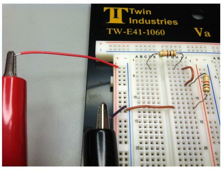
Clip the red alligator end to the free end of the red wire you used in Step 1. Clip the black alligator end to the free end of the black or blue wire you used in Step 1. My circuit is shown in the following figure.
Simple Circuit with Voltage Source Connections
Check to make sure that no metal parts of the alligator clips touch each other, and that they are connected to different columns of the “+” and “” connections.
Turn on the Agilent output.
Change the multimeter to the 20VDC measurement range. Use the multimeter to measure the voltage between the red and black alligator clips. What should this voltage be? Does it agree with the Agilent output? Why or why not?
With the range unchanged, use the multimeter to measure the voltage across each resistor. How do these voltages compare with the Agilent output? If you got a negative voltage, why was it negative? Reverse the red and black probes and try again. What changed?
Turn the Agilent output off.
Unclip the red alligator clip.
Change the multimeter to the 200mA setting.
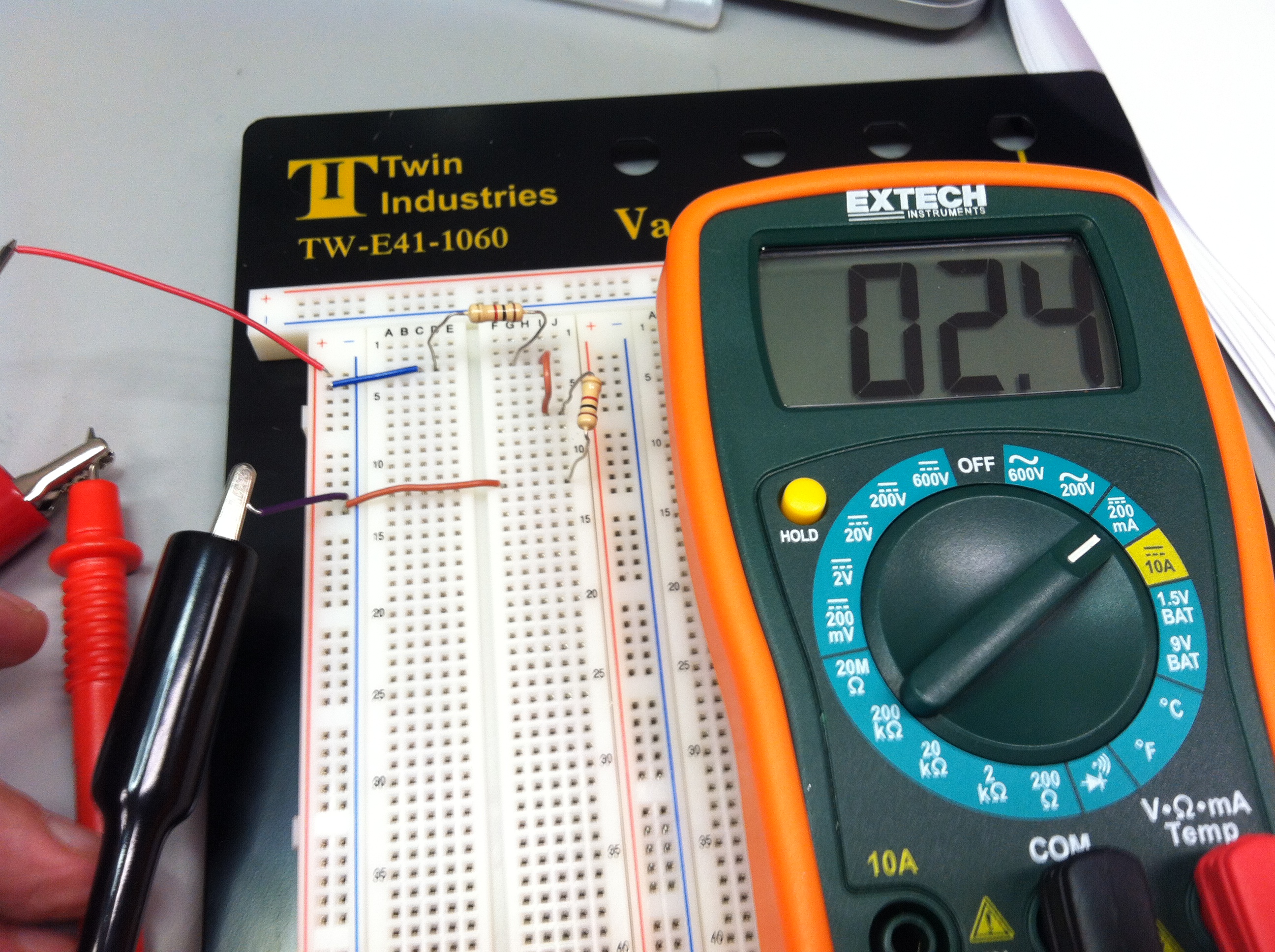
Clip the red alligator clip to end of the red probe. At this point, your circuit should look like following figure, although your multimeter won’t have any reading until after step 17.
Current Measurement Note the setting of the multimeter is 200 mA.
The black probe of the multimeter is just visible touching the red wire in the upper left of the photo. The black alligator clip has not moved. The red alligator clip is on the red probe of the multimeter.
Turn on the Agilent supply output.
Touch the black clip to the end of the red wire from Step 20. Is the multimeter connected in series or parallel with the circuit? What is
the measured current delivered to the circuit from the Agilent? Does
this make any sense according to Ohm’s Law?
Turn off the Agilent output.
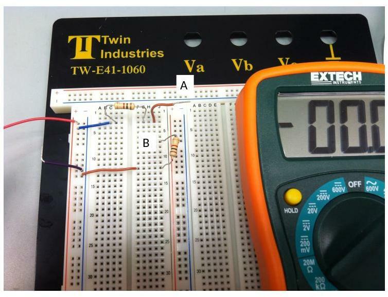
Reconnect the red alligator clip to the red wire. Pull one end of the short wire from Step 3 out of the breadboard, but leave the other end in the breadboard. Call this end “A”. Call the end of resistor connected in the same row as A “B”.Your circuit should look like the following figure.
Setup for measuring current between resistors
Note: This is a useful technique when you want to measure current within a circuit. Place a wire in series with your circuit elements so that you can easily break the circuit and insert the multimeter in *series* for the current measurement.**
Turn on the Agilent output. Connect the multimeter in series between “A” and “B”. Measure the current flowing between A and B. What is the measured current through this portion of the circuit. How does it compare with the value measured in Step 17?
📝 TA Verification
Have the TA check and record your completion.
Tear Down and Clean Up
At the end of every lab session, you are responsible for the following.
Turn off all test equipment. You may leave the computer on.
Deconstruct your circuit and save the wires and components in your kit. You will need the wires and components throughout the course, so don’t lose them.
Return the multimeter and the breadboard in accordance with TA instructions.
Return the cables to the proper racks and hang them neatly. Remember, others need to use the same cables, so put them away in the right places.
Clean up any mess in your lab station, including paper scraps, etc. This includes the floor!
Grading
Each lab document will provide a breakdown of the grading distribution. The distribution may vary each week. Lab completion is generally assessed through the lab report, but it may also include specific in-lab instructor/TA verification that will be recorded by the TA. Each week be sure to read the requirements for the lab report since it will provide guidance on documentation required to receive credit for lab completion. If you complete the lab but do not submit the lab report, you could forfeit all credit for lab completion.
Pre-Lab Assignment: (20 pts)
Each week, check Blackboard for assignment. It must be completed by 9:00 AM on Friday unless otherwise stated.
This week, for this initial week there is not a separate submission for the prelab. Include answers and responses only in your lab report.
Lab completion
TA-Verification of Lab Completion: (10 pts)
Completion Assessment via Lab Report: (50 pts)
Lab Report: (20 pts)
See Requirements in this week’s Lab Report Section
Submit a single PDF via Blackboard
Lab Report
You will need to submit your lab report by Tuesday midnight following the Friday Lab. We expect all submissions through blackboard. Submission instructions will be provided.
The lab reports should use professional language, and the target audience for technical content should be a student the is not quite a peer, one with less experience than yourself. Try to represent what you learned, and mention details relevant for conducting the lab exercise and reproducing the results. Also, be upfront about work completed versus work not completed. Point out deviations from expected results, and provide educated guesses about causes.
This week, your lab report should included the following:
A brief description of your previous experience if any with electronics hardware and labs, including any physics lab experience. Mention the test and measurement equipment that you used. Mention electronics components used.
A drawing of the circuit that you built and measured in-lab.
A statement about your level of completion for the lab exercise.
Provide answers to any question posed in the lab document.