The first solution we will consider is with the 8086. It was already designed and in production, so it was decided to build a co-processor (also called a floating-point unit, or FPU) to do the floating-point instructions. This was not a perfect solution, but resulted in some design issues that we have to live with today.
The first issue was that there was a physical distance between the two chips. Distance equals time, the greater the distance, the greater the time required. The CPU then had to wait on the FPU to finish resulting in wasted time. In thoses days the CPUs were not fast!
The second issue is that they needed a way to determine which was a FPU instruction and which was a CPU instruction. All of the FPU instructions start with the letter 'F'. This is not a problem, but that is just why it is done that way.
Every time they created a new generation of CPUs, they had to created a new FPU to be teamed with the new CPU. Since it was X86 for the CPU, they made it the X87 for the FPU.
The price of the FPU was about equal to the cost of the CPU and the customers did not like having to spend the extra, plus other issues, so it was decided to move the FPU circuitry on to the CPU chip and make it an integrated solution. This started with the 80386, where there were two versions, one with the FPU (DX) and one without (SX). This continued with the 80486. Since then, there is only the version with the FPU on the CPU chip. While the hardware was changed, the programming essentially was not.
| CPU | FPU |
|---|---|
| 8086 | 8087 |
| 80186 | 80187 |
| 80286 | 80287 |
| 80386SX | 80387 |
| 80486SX | 80487 |
| type | Old Name | New Name | C equivalent | size (in bits) | Significant Digits | Approximate Range |
|---|---|---|---|---|---|---|
| short floating point | DD | REAL4 | float | 32 | 6-7 | 1.18 x 10-38 to 3.40 x 1038 |
| long floating point | DQ | REAL8 | double | 64 | 15-16 | 2.23 x 10-380 to 1.79 x 10308 |
| integer | DW | WORD | short int | 16 | ||
| long integer | DD | DWORD | long int | 32 | ||
| *extended floating point | N/A | N/A | NONE | 80 |
* Internal format only
OK, so what does a floating-point number look like when using assembly language? First of all, we are not going to worry about what it actually looks like in memory!
| fp1 | REAL4 | 25.23 |
| fp2 | REAL8 | 2.523E1 |
| fp3 | REAL4 | -25.23 |
| fp4 | REAL8 | -2.523E1 |
| fp5 | REAL4 | 0.2523 |
| fp6 | REAL8 | 2.523E-1 |
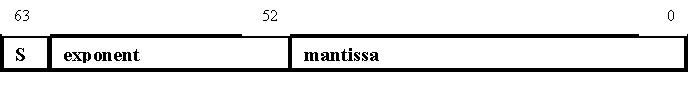
Let's look at 2.523E1. We have a mantissa and an exponent. The mantissa is 2.523, and the exponent is 1. They can be positive or negative and in any combination! Let's look at a REAL8 in detail.
There are three components in the long floating point:
The exponent is biased. That is value is in the range of -1023 to 1024. The bias is 1023, when added to the exponent results in a positive number. (If the exponent is 3, then 1026 is stored as the exponent portion of the floating point number.)
As you can see, this gives a very complex binary representation, so we will not worry about looking at it in any other form. When you become a more proficient assembly language programmer and want to look at the binary representation, you can ready the IEEE standard, IEEE Standard 754.
The proper instruction must be used with the proper data type
This same rule also applies when using indirect indexing for floating point values. When using CPU registers as
pointers to floating point data in memory, it is imperative that the index be qualified as pointing to the
appropriate size. Examples of using pointers to floating point data in memory when used with the proper FPU
instructions are:
dword ptr [esi+12] ;ESI would point to an array of REAL4 values
qword ptr [edi+ebx] ;EDI or EBX points to an array of REAL8 values
tbyte ptr [edx] ;EDX points to a REAL10 value
dword ptr [ebp+8] ;typical coding for pushed REAL4 parameters of procedures when coded by the assembler
ST(0), ST(1), ...., ST(7)
| Instruction Format | Syntax | Implied Operands | Example |
|---|---|---|---|
| Classical stack | Finstruction | ST, ST(1) | fadd |
| Memory | Finstruction memory | ST | fadd memloc |
| Register | Finstruction ST(num), ST Finstruction ST, ST(num) | -- | fadd st(5), st fadd st, st(3) |
| Register pop | FinstructionP ST(num), ST | -- |
With one exception, if the second letter in the instruction is an i, t working with an integer operand. (The exception is FINIT, tht initializes the FPU).
| Instruction(s) | D escription |
|---|---|
| FLD, FST, FSTP | Loads and stores real numbers |
| FILD, FIST, FISTP | Loads and stores integer numbers |
| FXCH | Exchanges register values |
| FLDZ | Pushes 0 into ST |
| FLD1 | Pushes 1 into ST |
| FLDPI | Pushes the value pi into ST |
| FLDL2E | Pushes the value of log2e into ST |
| FLD2T | Pushes the value of log210 into ST |
| FLDG2 | Pushes the value of loge2 into ST |
| Instruction(s) | Description |
|---|---|
| FADD, FADDP | Add/add and pop |
| FIADD | Integer add |
| FSUB/FSUBP | Subtract/subtract and pop |
| FSUBR/FSUBRP | Subtract/subtract and pop with reversed operands |
| FISUB | Integer subtract |
| FISUBR | Integer subtract with reversed operands |
| FDIV/FDIVP | Divide/divide and pop |
| FIDIV | Integer divide |
| FDIVR/FDIVRP | Divide/divide and pop with reversed operands |
| FIDIVR | Integer divide with reversed operands |
| FABS | |
| FCHS | |
| FRNDINT | |
| FSQRT |
| Instruction(s) | Description |
|---|---|
| FSIN | Calculate sine |
| FCOS | Calculate cosine |
| FSINCOS | Calculate quick sine and cosine |
| FPTAN | Calculate partial tangent |
| FPATAN | Calculate partial arctangent |
| FYL2X | Calculate y times log2 x |
| FYL2XP1 | Calculate y times log2 (x+1) |
| F2XM1 | calculate (2x)-1 |
| Instruction(s) | Description |
|---|---|
| FCOM | Compare |
| FCOMP | Compare and pop |
| FICOM | Integer compare |
| FTST | Integer compare and pop |
| FUCOM | Unordered compare |
| FUCOMP | Unordered compare and pop |
| FXAM | Set condition bits for value at top of stack |
| FSTSW | Store status word |