|
Electronic Thermometer Application report |

|
Application
|

|
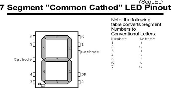
ELECTRONIC THERMOMETER This microcontroller application is used to display the current temperature in degrees Celsius. This digital thermometer uses a temperature sensing resistor (thermistor) and the temperature output is displayed on three seven segment LEDs. The circuit is driven by PIC16F84 using a 1-MHZ crystal oscillator. This Application measures the resistance of a thermistor, processes it with a Calibration value stored in the PIC (16C84) EEPROM and Displays it on three seven Segment Displays (in Degrees Celsius). The Calibration value can be changed while the thermometer is running. The thermometer itself is powered by a nine-volt alkaline radio battery using a "typical" thermistor and three seven segment LED displays. The code displays the current temperature in degrees Celsius. This application uses a resistor/ capacitor network to determine the resistance value of a thermistor. A thermistor is a semiconductor device whose resistance varies proportionally with variation in temperature. In this application the thermistor used is a 10k-thermistor with a negative temperature coefficient of -3.85%. This means that the thermistor's value decreases by 3.85% for each degree Celsius its temperature goes up. The seven-segment LED displays used are of a common cathode type which is to say that the cathodes of all the LEDs within the display are connected to common pins. That takes up a 14-pin 0.300” DIP pattern. The pin out of the conventional seven-segment LED display is shown below.
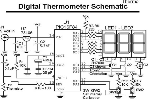
Fig1 seven-segment common-cathode light emitting diode ( LED) The operation of each different 7 Segment Display is controlled by a 2N70000 N-Channel MOSFET attached to the common cathode to the display. The gate to the controlling MOSFET is connected directly to an output PIN on the PIC. Each LED segment is connected to a PIC pin via a 220 ohm resistor, except for the segment connected to RA4, in which the 220 ohm resistor is attached to the power supply Vdd and the PIC pin pulls it low to turn off the LED. This is to avoid the issue of RA4 not being able to drive positive signals and it ensures that there is no possibility for high current to be sunk by RA4. this is done to avoid both the PIC microcontroller being burned out and to minimize the current consumption when RA4 is pulling the line low. This application is based on the following circuit design.
Fig 2 digital thermometer schematic by using PIC microcontroller. In the application circuit, RA’s and RB’s connections to the seven-segment LEDs RA2 is connected to segment 6 RA3 is connected to segment 5 RA4 is connected to segment 1 RB0 is connected to segment 7 RB1 is connected to segment 4 RB2 is connected to segment 3 RB3 is connected to segment 2 The DP (decimal point) pin of the LED display is left unconnected. The reason for using the above connections is to make the wiring easier. The seven current limiting resistors are placed between the PIC microcontroller and the LED displays. All of the display connections use the seven input/output pins on the left side of the PIC microcontroller. A useful strategy in the application-development process is to ensure that each subsystem in the application is tested before the final application is created. You can use assembly language to test the thermo application and programs to verify each facet of the design and assembly. The program simply cycles through the individual segments of the display to ensure that they are wired correctly. It is possible to test out the application by writing a short assembly code. This code will allow start checking the function of the thermistor/capacitor measuring circuit. formula to measures the resistance of thetmistor. Time = R * C –ln (Vend / Vstart) initially calculate the actual temperature, u can use idealize components and had a temperature looked from the table because the thermistor resistance versus temperature is a linear function; therefore it is not necessary to use extensive mathematical formula, The table relate the resistance value read use (where the time taken for the capacitor to discharge is proportional to the resistance) to an actual temperature. Table to show Resistiance versus Tempratore
In the actual application, a constant value used to shift the actual value returned into an accurate temperature value. Time = constant * R * C –ln (Vend / Vstart) the constant change the previous formula The next application test would be how to display values on the LEDs. The test should use an interrupt handler to toggle between the display (at 2k Hz) to give the appearance that they are all working at the same time. The interrupter handler makes the multiplexing between displays to be transparent to the mainline code. Al lit has to do is load up the values to be displayed for each digit and the interrupt handler takes care of the rest. Once the program start run, it display a value for the current temperature or an error message (uuu or ^^^) for to cold and to hot, respectively. While the circuit is up and running, it is easy to see the thermistor is working properly. You could put the themistor between your fingers and watch the temperature go up and down or put it into a refrigerator or freezer and watch it go down. In doing this, it is easy to tell that the themistor-baded thermometer will seem a lot faster than most mercury-based ones. That is because the thermistor has a lot smaller thermal mass than a mercury thermometer and it can reach its environment’s temperature faster. SW1 and SW2 are used to allow the user to change the calibration constant and shift the temperature displayed in different values and have stored them into the PIC microcontroller’s EEPROM.this controls switches are actually twin psots with one side connected to ground. When the connector are shorted to ground, the PIC microcontroller pins to which they are connected will be pulled to ground and used to change the constant value. There is 1/3 second delay to allow for debouncing and give a delay between updating the value and disconnecting the connection to the switch. The significant feature of the thermo assembly application code is how the date is stored in the EEPROM. On power up, two date-check bytes are checked for the values 0x0AA and 0x055. These date-check bytes are used to indicate that the value in the date EEPROM byte is actually correct. One of the first power up of the PIC microcontroller with this program, these memory locations are invalid and a separate set of code is executed to initialized the bytes along with the value byte means that if shut of the power of the PIC microcontroller . The calibration value itself is 16 bits long and is multiplied by the actual delay value. The high byte of the resulting 16 bit number is used as the corrected delay value. Using the high byte is the same as dividing the result by 256 (which is what the calibration value is based on). Doing the calculation this way eliminates the requirement to provide a division routine or floating point routines as part of the calibration. The table shows the material for the application. The project's Bill of Material is:
|