
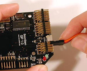
In the picture of the BrainStem below, the two pins on the bottom right of the board are for logic power. The lower of the two pins is ground (negative, typically the black wire from the battery). The upper of the two pins is power (positive, typically the red wire from the battery). It is crucial that you get power and ground to the right pins. Otherwise, you may irreparably damage the board. The two pins on the upper right side of the board are for servo power. Note which one is labeled ground (i.e., GND).
The connectors on either end of the power cable will fit on either of the sets of power pins. Cut the two wires of the power cable midway between the connectors. Strip about one half inch of insulation off the ends of the wires that you just cut (four in all). For one of the connectors, twist the bare part of the red wire with the bare part of the red wire on the 6V battery pack. Do the same with the black wires. Now cover the exposed bare wire with electrical tape. Turn the switch on the battery pack off and put batteries into the battery pack. Slide the connector onto the servo power pins ensuring that the black wire is on the pin labeled GND.
Repeat this process with the other half of the power cable and the 9V battery connector. However, rather than attaching the red wires directly to each other, attach them to the two contacts on the rocker switch. This may require soldering to get a good connection. Ask me if you want help with this (e.g., you don't have a soldering iron). It'll only take a minute. You'll also probably want to use electrical tape to ensure that the wires don't make contact with each other if they get bent. Turn the switch to the off position, snap in a 9V battery, and slide the connector onto the logic power pins ensuring that the black wire is on the pin labeled GND.
Once you get the BrainStem powered the right way, use the power switches. Don't remove the power cable connectors. That will prevent polarity errors that can lead to burned out boards, servos, and professors. If you turn on the 9V switch the red LED on the board should glow continuously. The green LED will flicker and go out.

Plug the connector into the 4 pins labeled SERIAL just below the servo power pins on the board. The word "Brainstem" on the connector should be facing up. Then connect the board to your machine with a serial cable.
If you don't have a serial port on your machine, which is probably the case, you'll need the Acroname USB serial interface connector.

Plug the connector into the SERIAL pins on the board, and connect the board to your machine with a USB cable. However, the software that communicates with the board still expects a serial port, so you'll need to download drivers that make the USB port look like a serial port. The drivers for Linux, Mac OS X, and Windows can be found here:
http://www.silabs.com/products/interface/usbtouart/Pages/default.aspx
Look for the link labeled "Virtual Com Port (VCP) Download" and click on it. It's on the right-hand side of the page under the heading "Design Resources". On the page that comes up find your operating system and click on the "VCP Driver Kit" link. The installation process should be self explanatory, but let me know if you need help.
Now use your username and password to log in, and click on the "View Software" button. There are two pages of software, so if you don't see what you want go to the next page.
First, get the BrainStem Reference, which will make a local copy of the HTML documentation for the BrainStem. It's small, and might be nice to have on your machine in cases when you don't have easy internet access (have you ever wanted to read micro-controller docs on your laptop while riding the DC metro?). Browse this for a while to see what's there.
Now get the "GP Support" software. After you unzip, untar, and un-whatever else is required, you'll have a folder named "acroname". Now navigate to acroname/aBinary where you'll find a number of files, including aGP (which is a GUI that allows you to do various things with the GP) and aConsole (which is a command line interface to the GP functionality).
The only thing left to do is edit the file gp.config in the aBinary directory. In that file there will be a line that looks like this:
#portname = COM1Remove the leading "#", which says the line is a comment, and replace COM1 with the name of the serial port on which you'll be communicating. On a Windows machine you can figure out what port name to use by going to the Device Manager and looking at what is listed under "Ports (COM and LPT)". On my machine there is an entry that looks like this:
Silicon Labs CP210x USB to UART Bridge (COM3)In this case the line in gp.config should look like this:
portname = COM3On a Mac or Linux machine do "ls /dev/tty.*". You'll get one or more files that show up, with one of them that looks something like "tty.SLAB_USBtoUART". Use that (or whatever shows up when you do the ls command) as your portname, like this:
portname = tty.SLAB_USBtoUARTYou'll also want to set the link type via a line that looks like this:
linktype = serialYou'll know when you get the config file right because when you do the GP application will not say "Serial Port Not Found" (or something like that) when you run it. So, try running the GP application. Ensure that the serial/USB cable and the power cables are connected. Turn on the 9V battery switch. Then run the aGP application. The green LED should start to pulse when the application runs, this is the "heartbeat", and there will be a heartbeat in the application window.
Turn on both power supplies, run the GP application, and click on the Servo tab. Move the slider associated with the servo (0 - 3) you plugged in and it should rotate. More details on the GP 1.0 application can be found here.
You'll want to look at a few different resources before you get started writing code. They include:
Write your code with a text editor, give it a .tea extension, and put the file in the aUser subdirectory of the brainstem directory. Below is an example TEA program I wrote that might be useful for a SumoBot gait.
/* An example SumoBot gait written in TEA
 *
 * Servo 0 lifts the SumoBot so the wheels can swing free
 * Servos 1 and 2 are attached to wheels
 * The gait goes like this:
 *   - Lift the SumoBot so the wheels can swing free
 *   - Rotate the wheels back
 *   - Lower the SumoBot
 *   - Rotate the wheels forward while in contact with ground plane
 *   - Repeat
 *
 */


#define NUM_STEPS 5   /* The number of steps the robot should take */
#define SECOND 10000  /* One second delay when passed to aCore_Sleep */

#include < aCore.tea >
#include < aServo.tea >


void main() {

  int i;

  /* Ensure servos have full range of motion */
  aServo_SetLimits(0, 0x0046);
  aServo_SetLimits(1, 0x0046);
  aServo_SetLimits(2, 0x0046);

  /* Mandatory 3 second delay */
  aCore_Sleep(3*SECOND);

  for (i = 0; i < NUM_STEPS; i++) {

    /* Lift the SumoBot and wait for servo to move.  Note cast on second
     * parameter, which is the position (0 - 255).  The compiler compains
     * if the case is not there.
     */
    aServo_SetAbsolute(0, (unsigned char)128);
    aCore_Sleep(SECOND);

    /*Rotate the wheels back and wait for servos to move */
    aServo_SetAbsolute(1, (unsigned char)0);
    aServo_SetAbsolute(2, (unsigned char)0);
    aCore_Sleep(SECOND);

    /* Lower the SumoBot and wait for servo to move */
    aServo_SetAbsolute(0, (unsigned char)0);
    aCore_Sleep(SECOND);

    /*Rotate the wheels forward and wait for servos to move */
    aServo_SetAbsolute(1, (unsigned char)255);
    aServo_SetAbsolute(2, (unsigned char)255);
    aCore_Sleep(SECOND);
  }

}
Note that because I make calls that start with aServo I include
aServo.tea, and likewise with aCore.tea.
With this file in the aUser directory, run the console application. It'll look something like this:
BrainStem Console Application
Version 1.0, build 100121
Copyright 1994-2010, Acroname Inc.
o brainstem>
Now, to compile the Gait program, run the steep compiler in the console as shown below:
brainstem> steep Gait.teaAfter steep has run, the window will look something like this:
TEA Compiler
(Tiny Embedded Applications)
steep version 1.0
Copyright 1994-2010, Acroname Inc.

steep succeeded
output file Gait.cup has 204 bytes
o brainstem>
Though the details may vary, such as the number of bytes, depending on which version of my code I compiled when I made the screen shot, there should now be a file named Gait.cup in aObject. The next step is to load the object file onto the BrainStem. To do that you need to know about modules and slots.
Your BrainStem GP 1.0 is a module. Acroname makes other modules, and multiple modules can be chained together and can communicate with one another and the console application. You have to tell the console the number of the module you want to load the program onto. For reasons that are unclear to me, your single GP 1.0 module is probably number 2.
Each module has number of program slots. The GP 1.0 module has 11 slots numbered 0 through 10. To download the Gait program to slot 0 on the BrainStem you issue this command in the console:
load Gait.cup 2 0That is, "load" the program named "Gait" into slot "0" of module "2". Finally, to run the program in slot 0 you issue this command in the console:
launch 2 0Note that when you load a program onto the BrainStem it resides in the module's EEPROM. If you turn the unit off, turn it back on, and just issue the launch command above, the Gait program will begin running.
The last thing to note is that when the control code for your SumoBot is fully debugged, you will probably want it to run when you switch on the BrainStem. See this article for information on how to make TEA programs run in this manner.
Note that it is possible to do a hardware reset of the BrainStem. Sometimes micro-controllers get confused, either due to bugs or erroneous commands sent to them. If your BrainStem starts to act "weird", try a hardware reset.