CS313 Selected Lecture Notes
This is one big WEB page, used for printing
 These are not intended to be complete lecture notes.
 Complicated figures or tables or formulas are included here
 in case they were not clear or not copied correctly in class.
 Source code may be included in line or by a link.

 Lecture numbers correspond to the syllabus numbering.
Lecture 1 Number Systems
Lecture 2 NASM
Lecture 3 Registers, Syntax and sections
Lecture 4 Arithmetic and shifting
Lecture 5 Using Debugger
Lecture 6 Branching and loops
Lecture 7 Subroutines and stacks
Lecture 8 Boot programs and 16-bit
Lecture 9 BIOS calls
Lecture 10 Hardware interface
Lecture 11 Privileged instructions
Lecture 12 Linux kernel calls
Lecture 13 Review
Lecture 14 Mid term exam
Lecture 15 Logic Gates
Lecture 16 Combinational logic
Lecture 17 Combinational logic design
Lecture 18 Simulation tools
Lecture 19 Arithmetic circuits
Lecture 20 Multiply and divide
Lecture 21 Karnaugh maps, Quine McClusky
Lecture 22 Flip-flops, latches, registers
Lecture 23 Sequential logic
Lecture 24 Computer organization
Lecture 25 Instruction set
Lecture 26 Data Paths
Lecture 27 Arithematic Logic Unit
Lecture 28 Architecture
Lecture 29 Review
Lecture 30 Final Exam
Other Links
You should be familiar with programming.
You edit your source code and have it on the disc.
A compiler reads your source code and typically converts
high level language to assembly language as another file on the disc.
The assembler reads the assembly language and produces a
binary object file with machine instructions.
The loader reads object files and creates an executable image.
This course is to provide a basic understanding of how computers
operate internally, e.g. computer architecture and assembly language.
Technically: The computer does not run a "program", the computer
has an operating system that runs a "process". A process starts
with loading the executable image of a program in memory.
A process sets up "segments" of memory with:
A ".text" segment with computer instructions
A ".data" segment with initialized data
A ".rodata" segment with initialized data, read only
A ".bss" segment for variables and arrays, block starting symbols
A "stack" for pushing and popping values
A "heap" for dynamically getting more memory
And then the process is executed by having the program
address register set to the first executable instruction
in the process. You will be directly using segments in
your assembly language programs.
Computers store bits, binary digits, in memory and we usually
read the bits, four at a time as hexadecimal. The basic unit
of storage in the computer is two hex digits, eight bits, a byte.
The data may be integers, floating point or characters.
We start this course with a thorough understanding of numbers.
For Intel assembly language: two bytes are a word.
four bytes are a double word, eight bytes are a quad word.
Todays computers are almost all 64 bit machines,
we will be programming using 64 bit quad words.
Numbers are represented as the coefficients of powers of a base.
(in plain text, we use "^" to mean, raise to power or exponentiation)
With no extra base indication, expect decimal numbers:
12.34 is a representation of
1*10^1 + 2*10^0 + 3*10^-1 + 4*10^-2 or
10
2
.3
+ .04
------
12.34
Binary numbers, in NASM assembly language, have a trailing B or b.
101.11B is a representation of
1*2^2 + 0*2^1 + 1*2^0 + 1*2^-1 + 1*2^-2 or
4
0
1
.5 (you may compute 2^-n or look up in table below)
+ .25
------
5.75
Converting a decimal number to binary may be accomplished:
Convert 12.34 from decimal to binary
Integer part Fraction part
quotient remainder integer fraction
12/2 = 6 0 .34*2.0 = 0.68 use fmul, fistp get 0
6/2 = 3 0 .68*2.0 = 1.36 use fmul, fistp get 1
3/2 = 1 1 .36*2.0 = 0.72
1/2 = 0 1 .72*2.0 = 1.44
done .44*2.0 = 0.88
read up 1100 .88*2.0 = 1.76
.76*2.0 = 1.52
.52*2.0 = 1.04
quit
read down .01010111
answer is 1100.01010111
convert.c "C" program sample to do conversions
"C" program output
; in nasm assembly language make fistp truncate rather than round
fstcw WORD [cwd] ; store the FPU control word
or WORD [cwd],0x0c00 ; set rounding mode to "truncate"
fldcw WORD [cwd] ; load updated control word
hint:nasm storing a floating point fraction into an integer loacation, fistp
0.68 becomes 0
1.36 becomes 1
0.72 becomes 0
1.44 becomes 1
integer 34 to 34.0, 34.0/100.0 = .34 floating point
then multiply by 2.0
Powers of 2
Decimal
n -n
2 n 2
1 0 1.0
2 1 0.5
4 2 0.25
8 3 0.125
16 4 0.0625
32 5 0.03125
64 6 0.015625
128 7 0.0078125
256 8 0.00390625
512 9 0.001953125
1024 10 0.0009765625
2048 11 0.00048828125
4096 12 0.000244140625
8192 13 0.0001220703125
16384 14 0.00006103515625
32768 15 0.000030517578125
65536 16 0.0000152587890625
For binary to decimal:
2^3 2^2 2^1 2^0 2^-1 2^-2 2^-3
1 1 1 1 . 1 1 1
8 + 4 + 2 + 1 + .5 + .25 + .125 = 15.875
Binary
n -n
2 n 2
1 0 1.0
10 1 0.1
100 2 0.01
1000 3 0.001
10000 4 0.0001
100000 5 0.00001
1000000 6 0.000001
10000000 7 0.0000001
100000000 8 0.00000001
1000000000 9 0.000000001
10000000000 10 0.0000000001
100000000000 11 0.00000000001
1000000000000 12 0.000000000001
10000000000000 13 0.0000000000001
100000000000000 14 0.00000000000001
1000000000000000 15 0.000000000000001
10000000000000000 16 0.0000000000000001
Hexadecimal
n -n
2 n 2
1 0 1.0
2 1 0.8
4 2 0.4
8 3 0.2
10 4 0.1
20 5 0.08
40 6 0.04
80 7 0.02
100 8 0.01
200 9 0.008
400 10 0.004
800 11 0.002
1000 12 0.001
2000 13 0.0008
4000 14 0.0004
8000 15 0.0002
10000 16 0.0001
Decimal to Hexadecimal to Binary, 4 bits per hex digit
0 0 0000
1 1 0001
2 2 0010
3 3 0011
4 4 0100
5 5 0101
6 6 0110
7 7 0111
8 8 1000
9 9 1001
10 A 1010
11 B 1011
12 C 1100
13 D 1101
14 E 1110
15 F 1111
n n
n 2 hexadecimal 2 decimal approx notation
10 400 1,024 10^3 K kilo
20 100000 1,048,576 10^6 M mega
30 40000000 1,073,741,824 10^9 G giga
40 10000000000 1,099,511,627,776 10^12 T tera
The three representations of negative numbers that have been
used in computers are twos complement, ones complement and
sign magnitude. In order to represent negative numbers, it must
be known where the "sign" bit is placed. All modern binary
computers use the leftmost bit of the computer word as a sign bit.
The examples below use a 4-bit register to show all possible
values for the three representations.
decimal twos complement ones complement sign magnitude
0 0000 0000 0000
1 0001 0001 0001
2 0010 0010 0010
3 0011 0011 0011
4 0100 0100 0100
5 0101 0101 0101
6 0110 0110 0110
7 0111 0111 0111 all same for positive
-7 1001 1000 1111
-6 1010 1001 1110
-5 1011 1010 1101
-4 1100 1011 1100
-3 1101 1100 1011
-2 1110 1101 1010
-1 1111 1110 1001
-8 1000 -0 1111 -0 1000
^ / ^|||
\_ add 1 _/ sign__/ --- magnitude
To get the sign magnitude, convert the decimal to binary and
place a zero in the sign bit for positive, place a one in the
sign bit for negative.
To get the ones complement, convert the decimal to binary,
including leading zeros, then invert every bit. 1->0, 0->1.
To get the twos complement, get the ones complement and add 1.
(Throw away any bits that are outside of the register)
It may seem silly to have a negative zero, but it is
mathematically incorrect to have -(-8) = -8
Then, if you must use Roman Numerals roman.shtml
or roman_numeral.shtml
Size in bytes, names and power of 10 approximate power of 2 power.shtml
IEEE Floating point formats
Almost all Numerical Computation arithmetic is performed using
IEEE 754-1985 Standard for Binary Floating-Point Arithmetic.
The two formats that we deal with in practice are the 32 bit and
64 bit formats.
IEEE Floating-Point numbers are stored as follows:
The single format 32 bit has
1 bit for sign, 8 bits for exponent, 23 bits for fraction
The double format 64 bit has
1 bit for sign, 11 bits for exponent, 52 bits for fraction
There is actually a '1' in the 24th and 53rd bit to the left
of the fraction that is not stored. The fraction including
the non stored bit is called a significand.
The exponent is stored as a biased value, not a signed value.
The 8-bit has 127 added, the 11-bit has 1023 added.
A few values of the exponent are "stolen" for
special values, +/- infinity, not a number, etc.
Floating point numbers are sign magnitude. Invert the sign bit to negate.
Some example numbers and their bit patterns:
decimal
stored hexadecimal sign exponent fraction significand
bit in binary
The "1" is not stored
| biased
31 30....23 22....................0 exponent
2.0
40 00 00 00 0 10000000 00000000000000000000000 1.0 * 2^(128-127)
1.0
3F 80 00 00 0 01111111 00000000000000000000000 1.0 * 2^(127-127)
0.5
3F 00 00 00 0 01111110 00000000000000000000000 1.0 * 2^(126-127)
0.75
3F 40 00 00 0 01111110 10000000000000000000000 1.1 * 2^(126-127)
0.9999995
3F 7F FF FF 0 01111110 11111111111111111111111 1.1111* 2^(126-127)
0.1
3D CC CC CD 0 01111011 10011001100110011001101 1.1001* 2^(123-127)
The "1" is not stored
|
63 62...... 52 51 ..... 0
2.0
40 00 00 00 00 00 00 00 0 10000000000 000 ... 000 1.0 * 2^(1024-1023)
1.0
3F F0 00 00 00 00 00 00 0 01111111111 000 ... 000 1.0 * 2^(1023-1023)
0.5
3F E0 00 00 00 00 00 00 0 01111111110 000 ... 000 1.0 * 2^(1022-1023)
0.75
3F E8 00 00 00 00 00 00 0 01111111110 100 ... 000 1.1 * 2^(1022-1023)
0.9999999999999995
3F EF FF FF FF FF FF FF 0 01111111110 111 ... 1.11111* 2^(1022-1023)
0.1
3F B9 99 99 99 99 99 9A 0 01111111011 10011..1010 1.10011* 2^(1019-1023)
|
sign exponent fraction |
before storing subtract bias
Note that an integer in the range 0 to 2^23 -1 may be represented exactly.
Any power of two in the range -126 to +127 times such an integer may also
be represented exactly. Numbers such as 0.1, 0.3, 1.0/5.0, 1.0/9.0 are
represented approximately. 0.75 is 3/4 which is exact.
Some languages are careful to represent approximated numbers
accurate to plus or minus the least significant bit.
Other languages may be less accurate.
The operations of add, subtract, multiply and divide are defined as:
Given x1 = 2^e1 * f1
x2 = 2^e2 * f2 and e2 <= e1
x1 + x2 = 2^e1 *(f1 + 2^-(e1-e2) * f2) f2 is shifted then added to f1
x1 - x2 = 2^e1 *(f1 - 2^-(e1-e2) * f2) f2 is shifted then subtracted from f1
x1 * x2 = 2^(e1+e2) * f1 * f2
x1 / x2 = 2^(e1-e2) * (f1 / f2)
an additional operation is usually needed, normalization.
if the resulting "fraction" has digits to the left of the binary
point, then the fraction is shifted right and one is added to
the exponent for each bit shifted until the result is a fraction.
IEEE 754 Floating Point Standard
Strings of characters
We will use one of many character representations for
character strings, ASCII, one byte per character in a string.
symbol or name symbol or key stroke
key stroke
hexadecimal hexadecimal
decimal decimal
NUL ^@ 00 0 Spc 20 32 @ 40 64 ` 60 96
SOH ^A 01 1 ! 21 33 A 41 65 a 61 97
STX ^B 02 2 " 22 34 B 42 66 b 62 98
ETX ^C 03 3 # 23 35 C 43 67 c 63 99
EOT ^D 04 4 $ 24 36 D 44 68 d 64 100
ENQ ^E 05 5 % 25 37 E 45 69 e 65 101
ACK ^F 06 6 & 26 38 F 46 70 f 66 102
BEL ^G 07 7 ' 27 39 G 47 71 g 67 103
BS ^H 08 8 ( 28 40 H 48 72 h 68 104
TAB ^I 09 9 ) 29 41 I 49 73 i 69 105
LF ^J 0A 10 * 2A 42 J 4A 74 j 6A 106
VT ^K 0B 11 + 2B 43 K 4B 75 k 6B 107
FF ^L 0C 12 , 2C 44 L 4C 76 l 6C 108
CR ^M 0D 13 - 2D 45 M 4D 77 m 6D 109
SO ^N 0E 14 . 2E 46 N 4E 78 n 6E 110
SI ^O 0F 15 / 2F 47 O 4F 79 o 6F 111
DLE ^P 10 16 0 30 48 P 50 80 p 70 112
DC1 ^Q 11 17 1 31 49 Q 51 81 q 71 113
DC2 ^R 12 18 2 32 50 R 52 82 r 72 114
DC3 ^S 13 19 3 33 51 S 53 83 s 73 115
DC4 ^T 14 20 4 34 52 T 54 84 t 74 116
NAK ^U 15 21 5 35 53 U 55 85 u 75 117
SYN ^V 16 22 6 36 54 V 56 86 v 76 118
ETB ^W 17 23 7 37 55 W 57 87 w 77 119
CAN ^X 18 24 8 38 56 X 58 88 x 78 120
EM ^Y 19 25 9 39 57 Y 59 89 y 79 121
SUB ^Z 1A 26 : 3A 58 Z 5A 90 z 7A 122
ESC ^[ 1B 27 ; 3B 59 [ 5B 91 { 7B 123
LeftSh 1C 28 < 3C 60 \ 5C 92 | 7C 124
RighSh 1D 29 = 3D 61 ] 5D 93 } 7D 125
upAro 1E 30 > 3E 62 ^ 5E 94 ~ 7E 126
dnAro 1F 31 ? 3F 63 _ 5F 95 DEL 7F 127
Optional future installation on your personal computer
Throughout this course, we will be writing some assembly language.
This will be for an Intel or Intel compatible computer, e.g. AMD.
The assembler program is "nasm" and can be run on
linux.gl.umbc.edu or on your computer.
If you are running linux on your computer, the command
sudo apt-get install nasm
will install nasm on your computer.
Throughout this course we will work with digital logic and
cover basic VHDL and verilog languages for describing
digital logic. There are free simulators, that will
simulate the operation of your digital logic for both languages
and graphical input simulator logisim.
The commands for installing these on linux are:
sudo apt-get install freehdl
or use Makefile_vhdl from my download directory on linux.gl.umbc.edu
sudo apt-get install iverilog
or use Makefile_verilog from my download directory on linux.gl.umbc.edu
from www.cburch.com/logisim/index.html get logisim
or use Makefile_logisim from my download directory on linux.gl.umbc.edu
These or similar programs may be available for installing
on some versions of Microsoft Windows or Mac OSX.
We will use 64-bit in this course, to expand your options.
In "C" int remains a 32-bit number although we have 64-bit computers
and 64-bit operating systems and 64-bit computers that are still
programmed as 32-bit computers.
test_factorial.c uses int, outputs:
test_factorial.c using int, note overflow
0!=1
1!=1
2!=2
3!=6
4!=24
5!=120
6!=720
7!=5040
8!=40320
9!=362880
10!=3628800
11!=39916800
12!=479001600
13!=1932053504 BAD
14!=1278945280
15!=2004310016
16!=2004189184
17!=-288522240
18!=-898433024
test_factorial_long.c uses long int, outputs:
test_factorial_long.c using long int, note overflow
0!=1
1!=1
2!=2
3!=6
4!=24
5!=120
6!=720
7!=5040
8!=40320
9!=362880
10!=3628800
11!=39916800
12!=479001600
13!=6227020800
14!=87178291200
15!=1307674368000
16!=20922789888000
17!=355687428096000
18!=6402373705728000
19!=121645100408832000
20!=2432902008176640000
21!=-4249290049419214848 BAD
22!=-1250660718674968576
Well, 13! wrong vs 21! wrong may not be a big deal.
factorial.py by default, outputs:
factorial(0)= 1
factorial(1)= 1
factorial(2)= 2
factorial(3)= 6
factorial(4)= 24
factorial(52)= 80658175170943878571660636856403766975289505440883277824000000000000
Yet, 32-bit signed numbers can only index 2GB of ram, 64-bit are
needed for computers with 4GB, 8GB, 16GB, 32GB etc of ram, available today.
95% of all supercomputers, called HPC, are 64-bit running Linux.
A first quick look at assembly language:
In high order language, A = B + C;
You think of adding the value of C to B and storing in A
In assembly language you think of A, B, and C as addresses.
You load the contents of address B into a register.
You add the contents of address C to that register.
You store that register at address A.
Well, Intel uses the word move, typed mov, for load and store.
mov rax,[B] ; semicolon starts a comment (no end of statement symbol)
add rax,[C] ; the [ ] says "contents of address"
mov [A],rax ; the mov is from second field to first field
; hello_64.asm print a string using printf
; Assemble: nasm -f elf64 -l hello_64.lst hello_64.asm
; Link: gcc -m64 -o hello_64 hello_64.o
; Run: ./hello_64 > hello_64.out
; Output: cat hello_64.out
; Equivalent C code
; // hello.c
; #include <stdio.h>
; int main()
; {
; char msg[] = "Hello world";
; printf("%s\n",msg);
; return 0;
; }
; Declare needed C functions
extern printf ; the C function, to be called
section .data ; Data section, initialized variables
msg: db "Hello world", 0 ; C string needs 0
fmt: db "%s", 10, 0 ; The printf format, "\n",'0'
section .text ; Code section.
global main ; the standard gcc entry point
main: ; the program label for the entry point
push rbp ; set up stack frame, must be aligned
mov rdi,fmt ; address of format, standard register rdi
mov rsi,msg ; address of first data, standard register rsi
mov rax,0 ; or can be xor rax,rax
call printf ; Call C function
; printf can mess up many registers
; save and reload registers with debug print
pop rbp ; restore stack
mov rax,0 ; normal, no error, return value
ret ; return
hello_64.lst with many comments removed
20 section .data ; Data section, initialized variables
21 00000000 48656C6C6F20776F72- msg: db "Hello world", 0 ; C string needs 0
22 00000009 6C6400
23 0000000C 25730A00 fmt: db "%s", 10, 0 ; The printf format, "\n",'0'
24
25 section .text ; Code section.
26
27 global main ; the standard gcc entry point
28 main: ; the program label for the entry point
29 00000000 55 push rbp ; set up stack frame, must be aligned
30
31 00000001 48BF- mov rdi,fmt ; address of format, standard register rdi
32 00000003 [0C00000000000000]
33 0000000B 48BE- mov rsi,msg ; address of first data, standard register rsi
34 0000000D [0000000000000000]
35 00000015 B800000000 mov rax,0 ; or can be xor rax,rax
36 0000001A E8(00000000) call printf ; Call C function
37
38 0000001F 5D pop rbp ; restore stack
39
40 00000020 B800000000 mov rax,0 ; normal, no error, return value
41 00000025 C3 ret ; return
You do not need C, computers come with BIOS.
; bios1.asm use BIOS interrupt for printing
; Compiled and run using one Linux command line
; nasm -f elf64 bios1.asm && ld bios1.o && ./a.out
global _start ; standard ld main program
section .text
_start:
print1: mov rax,[ahal]
int 10h ; write character to screen.
mov rax,[ret]
int 10h ; write new line '\n'
mov rax,0
ret
ahal: dq 0x0E28 ; output to screen ah has 0E
ret: dq 0x0E0A ; '\n'
; end bios1.asm
First homework assigned
on web, www.cs.umbc.edu/~squire/cs313_hw.shtml
Due in one week. Best to do right after lecture.
A 64-bit architecture, by definition, has 64-bit integer registers.
Here are sample programs and output to test for 64-bit capability in gcc:
Get sizeof on types and variables big.c
output from  gcc -m64 big.c  big.out
malloc more than 4GB  big_malloc.c
output from  big_malloc_mac.out
Newer Operating Systems and compilers
Get sizeof on types and variables big12.c
output from  gcc big12.c  big12.out
To bring everyone into the 64-bit world, we will use all 64-bit programs.

A note about the Intel computer architecture and the
tradeoff between "upward compatibility" and "clinging to the past".
Intel built a  4-bit computer 4004.
Intel built an 8-bit, byte, computer 8008
Intel built a 16-bit, word, computer 8086
Intel built a 32-bit, double word, computer 80386
Intel builds  64-bit, quad word, computers X86-64
The terms byte, word, double word, and quad word remain today
in the software we will write for modern 64-bit computers.
We use  -f elf64  and  -m64  for assembling and compiling

Learning a new programming language is an orderly progression
of steps.
1) Find sample code that you can compile and run to get output
   This is typically  hello_world  or just hello
   Then more output, we use  "C" printf  printf1.asm  printf2.asm
2) Find sample code for defining data of the types supported
   We use  testdata_64.asm for Nasm assembly language
3) Find sample code to do integer arithmetic
   We use  intarith_64.asm
4) Find sample code to do floating point arithmetic
   We use  fltarith_64.asm
5) Find sample code to write a function and call a function
   We use  fib_64.asm or test_factorial.asm
Along the way, you will see the structure of typical code,
and initialization and termination of typical programs,
creating "if" and "loop" constructs. Then you can
"cut-and-paste" existing code, modify for your program.

Computer access for this course
NASM is installed on  linux.gl.umbc.edu  and can be used there.

From anywhere that you can reach the internet, log onto your
UMBC account using:

    ssh  your-user-id@linux.gl.umbc.edu
    your-password


You should set up a directory for CMSC 313 and keep all your
course work in one directory.

  e.g.    mkdir  cs313  # only once
          cd  cs313     # change to directory each time for CMSC 313

Copy over a sample program to your directory using:

 cp /afs/umbc.edu/users/s/q/squire/pub/download/hello_64.asm  .


Assemble hello.asm using:

  nasm -f elf64 hello_64.asm

Link to create an executable using:

  gcc -m64 -o hello  hello_64.o

Execute the program using:

  hello  or  ./hello

Assembly Language
Assembly Language is written as lines, rather than statements.
A semicolon makes the rest of a line a comment.
A line may be blank, a comment, a machine instruction or
an assembler directive called a pseudo instruction.
An optional label may start a line with a colon.
An assembly language program can run on a bare computer,
can run directly on an operating system, or can run using
a compiler and associated libraries. We will use a C compiler
and libraries for convenience.

A big difference between assembly language and compiler code
is that a label for a variable in assembly language is an address
while a name of a variable in compiler code is the value.

Assembly language programmers are very frugal.
They typically minimize storage space and time.
e.g. the instructions  xor rax,rax    mov rax,0  do the same
thing, zero register rax yet the xor is a little faster.
e.g. many variables are never stored in RAM, they keep values in registers.
I will avoid many of these "tricks" for a while.
(Files are available as hello.asm and hello_64.asm,
 the  _64  is to emphasize we will use all 64-bit values and registers.
 Usually there is also a C language file, e.g. hello.c )

First example  hello_64.asm
Now look at the file hello_64.asm

; hello_64.asm       print a string using printf
; Assemble:	  nasm -f elf64 -l hello_64.lst  hello_64.asm
; Link:		  gcc -m64 -o hello  hello_64.o
; Run:		  ./hello > hello.out
; Output:	  cat hello.out

; Equivalent C code
; // hello.c
; #include <stdio.h>
; int main()
; {
;   char msg[] = "Hello world";
;   printf("%s\n",msg);
;   return 0;
; }

; Declare needed C  functions
        extern	printf		; the C function, to be called

        section .data		; Data section, initialized variables
msg:	db "Hello world", 0	; C string needs 0
fmt:    db "%s", 10, 0          ; The printf format, "\n",'0'

        section .text           ; Code section.

        global main		; the standard gcc entry point
main:				; the program label for the entry point
        push    rbp		; set up stack frame, must be aligned

	mov	rdi,fmt		; pass format, standard register rdi
	mov	rsi,msg		; pass first parameter, standard register rsi
	mov	rax,0		; or can be  xor  rax,rax
        call    printf		; Call C function

        pop     rbp		; restore stack

	mov	rax,0		; normal, no error, return value
	ret			; return


Makefile_nasm
Now, to save yourself typing, download  Makefile_nasm into
your cs313 directory. There will be more sample files to download.

cp /afs/umbc.edu/users/s/q/squire/pub/download/Makefile_nasm  Makefile
make  # look in Makefile to see how to add more files to run

Type  make  # to run Makefile, only changed stuff gets run
Type  make -f Makefile_nasm  # only changed stuff gets run


Variable Data and Storage allocation, sections
There can be many types of data in the  ".data" section:
Look at the file testdata_64.asm
and see the results in testdata_64.lst

; testdata_64.asm  a program to demonstrate data types and values
; assemble:	nasm -f elf64 -l testdata_64.lst  testdata_64.asm
; link:		gcc -m64 -o testdata_64  testdata_64.o
; run:	        ./testdata_64
; Look at the list file, testdata_64.lst
; no output
; Note! nasm ignores the type of data and type of reserved
; space when used as memory addresses.
; You may have to use qualifiers BYTE, WORD, DWORD or QWORD

	section .data		; data section
				; initialized, writeable

				; db for data byte, 8-bit
db01:	db	255,1,17	; decimal values for bytes
db02:	db	0xff,0ABh	; hexadecimal values for bytes
db03:	db	'a','b','c'	; character values for bytes
db04:	db	"abc"		; string value as bytes 'a','b','c'
db05:	db	'abc'		; same as "abc" three bytes
db06:	db	"hello",13,10,0 ; "C" string including cr and lf

				; dw for data word, 16-bit
dw01:	dw	12345,-17,32	; decimal values for words
dw02:	dw	0xFFFF,0abcdH	; hexadecimal values for words
dw03:	dw	'a','ab','abc'	; character values for words
dw04:	dw	"hello"		; three words, 6-bytes allocated

				; dd for data double word, 32-bit
dd01:	dd	123456789,-7	; decimal values for double words
dd02:	dd	0xFFFFFFFF	; hexadecimal value for double words
dd03:	dd	'a'		; character value in double word
dd04:	dd	"hello"		; string in two double words
dd05:	dd	13.27E30	; floating point value 32-bit IEEE

				; dq for data quad word, 64-bit
dq01:	dq	123456789012,-7	; decimal values for quad words
dq02:	dq	0xFFFFFFFFFFFFFFFF ; hexadecimal value for quad words
dq03:	dq	'a'		; character value in quad word
dq04:	dq	"hello_world"	; string in two quad words
dq05:	dq	13.27E300	; floating point value 64-bit IEEE

				; dt for data ten of 80-bit floating point
dt01:	dt	13.270E3000	; floating point value 80-bit in register


	section .bss		; reserve storage space
				; uninitialized, writeable

s01:	resb	10		; 10 8-bit bytes reserved
s02:	resw	20		; 20 16-bit words reserved
s03:	resd	30		; 30 32-bit double words reserved
s04:	resq	40		; 40 64-bit quad words reserved
s05:	resb	1		; one more byte

	SECTION .text		; code section
        global main		; make label available to linker
main:				; standard  gcc  entry point

	push	rbp		; initialize stack

	mov	al,[db01]	; correct to load a byte
	mov	ah,[db01]	; correct to load a byte
	mov	ax,[dw01]	; correct to load a word
	mov	eax,[dd01]	; correct to load a double word
	mov	rax,[dq01]	; correct to load a quad word

	mov	al,BYTE [db01]	; redundant, yet allowed
	mov	ax,[db01]	; no warning, loads two bytes
	mov	eax,[dw01]	; no warning, loads two words
	mov	rax,[dd01]	; no warning, loads two double words

;	mov	ax,BYTE [db01]	; error, size miss match
;	mov	eax,WORD [dw01]	; error, size miss match
;	mov	rax,WORD [dd01]	; error, size miss match

;	push	BYTE [db01]	; error, can not push a byte
	push	WORD [dw01]	; "push" needs to know size 2-byte
;	push	DWORD [dd01]	; error, can not push a 4-byte
	push	QWORD [dq01]	; OK

;	push	eax		; error, wrong size, need 64-bit
	push	rax

	fld	DWORD [dd05]	; floating load 32-bit
	fld	QWORD [dq05]	; floating load 64-bit

	mov	rbx,0		; exit code, 0=normal
	mov	rax,1		; exit command to kernel
	int	0x80		; interrupt 80 hex, call kernel

; end testdata_64.asm


Widen your browser window, part of testdata_64.lst
to see addresses and data values in hexadecimal.

     1                                  ; testdata_64.asm  a program to demonstrate data types and values
     2                                  ; assemble:	nasm -f elf64 -l testdata_64.lst  testdata_64.asm
     3                                  ; link:		gcc -m64 -o testdata_64  testdata_64.o
     4                                  ; run:	        ./testdata_64
     5                                  ; Look at the list file, testdata_64.lst
     6                                  ; no output
     7                                  ; Note! nasm ignores the type of data and type of reserved
     8                                  ; space when used as memory addresses.
     9                                  ; You may have to use qualifiers BYTE, WORD, DWORD or QWORD
    10
    11                                  	section .data		; data section
    12                                  				; initialized, writeable
    13
    14                                  				; db for data byte, 8-bit
    15 00000000 FF0111                  db01:	db	255,1,17	; decimal values for bytes
    16 00000003 FFAB                    db02:	db	0xff,0ABh	; hexadecimal values for bytes
    17 00000005 616263                  db03:	db	'a','b','c'	; character values for bytes
    18 00000008 616263                  db04:	db	"abc"		; string value as bytes 'a','b','c'
    19 0000000B 616263                  db05:	db	'abc'		; same as "abc" three bytes
    20 0000000E 68656C6C6F0D0A00        db06:	db	"hello",13,10,0 ; "C" string including cr and lf
    21
    22                                  				; dw for data word, 16-bit
    23 00000016 3930EFFF2000            dw01:	dw	12345,-17,32	; decimal values for words
    24 0000001C FFFFCDAB                dw02:	dw	0xFFFF,0abcdH	; hexadecimal values for words
    25 00000020 6100616261626300        dw03:	dw	'a','ab','abc'	; character values for words
    26 00000028 68656C6C6F00            dw04:	dw	"hello"		; three words, 6-bytes allocated
    27
    28                                  				; dd for data double word, 32-bit
    29 0000002E 15CD5B07F9FFFFFF        dd01:	dd	123456789,-7	; decimal values for double words
    30 00000036 FFFFFFFF                dd02:	dd	0xFFFFFFFF	; hexadecimal value for double words
    31 0000003A 61000000                dd03:	dd	'a'		; character value in double word
    32 0000003E 68656C6C6F000000        dd04:	dd	"hello"		; string in two double words
    33 00000046 AF7D2773                dd05:	dd	13.27E30	; floating point value 32-bit IEEE
    34
    35                                  				; dq for data quad word, 64-bit
    36 0000004A 141A99BE1C000000F9-     dq01:	dq	123456789012,-7	; decimal values for quad words
    36 00000053 FFFFFFFFFFFFFF
    37 0000005A FFFFFFFFFFFFFFFF        dq02:	dq	0xFFFFFFFFFFFFFFFF ; hexadecimal value for quad words
    38 00000062 6100000000000000        dq03:	dq	'a'		; character value in quad word
    39 0000006A 68656C6C6F5F776F72-     dq04:	dq	"hello_world"	; string in two quad words
    39 00000073 6C640000000000
    40 0000007A C86BB752A7D0737E        dq05:	dq	13.27E300	; floating point value 64-bit IEEE
    41
    42                                  				; dt for data ten of 80-bit floating point
    43 00000082 4011E5A59932D5B6F0-     dt01:	dt	13.270E3000	; floating point value 80-bit in register
    43 0000008B 66
    44
    45
    46                                  	section .bss		; reserve storage space
    47                                  				; uninitialized, writeable
    48
    49 00000000           s01:	resb	10		; 10 8-bit bytes reserved
    50 0000000A           s02:	resw	20		; 20 16-bit words reserved
    51 00000032           s03:	resd	30		; 30 32-bit double words reserved
    52 000000AA           s04:	resq	40		; 40 64-bit quad words reserved
    53 000001EA           s05:	resb	1		; one more byte
    54
    55                                  	SECTION .text		; code section
    56                                          global main		; make label available to linker
    57                                  main:				; standard  gcc  entry point
    58
    59 00000000 55                      	push	rbp		; initialize stack
    60
    61 00000001 8A0425[00000000]        	mov	al,[db01]	; correct to load a byte
    62 00000008 8A2425[00000000]        	mov	ah,[db01]	; correct to load a byte
    63 0000000F 668B0425[16000000]      	mov	ax,[dw01]	; correct to load a word
    64 00000017 8B0425[2E000000]        	mov	eax,[dd01]	; correct to load a double word
    65 0000001E 488B0425[4A000000]      	mov	rax,[dq01]	; correct to load a quad word
    66
    67 00000026 8A0425[00000000]        	mov	al,BYTE [db01]	; redundant, yet allowed
    68 0000002D 668B0425[00000000]      	mov	ax,[db01]	; no warning, loads two bytes
    69 00000035 8B0425[16000000]        	mov	eax,[dw01]	; no warning, loads two words
    70 0000003C 488B0425[2E000000]      	mov	rax,[dd01]	; no warning, loads two double words
    71
    72                                  ;	mov	ax,BYTE [db01]	; error, size miss match
    73                                  ;	mov	eax,WORD [dw01]	; error, size miss match
    74                                  ;	mov	rax,WORD [dd01]	; error, size miss match
    75
    76                                  ;	push	BYTE [db01]	; error, can not push a byte
    77 00000044 66FF3425[16000000]      	push	WORD [dw01]	; "push" needs to know size 2-byte
    78                                  ;	push	DWORD [dd01]	; error, can not push a 4-byte
    79 0000004C FF3425[4A000000]        	push	QWORD [dq01]	; OK
    80
    81                                  ;	push	eax		; error, wrong size, need 64-bit
    82 00000053 50                      	push	rax
    83
    84 00000054 D90425[46000000]        	fld	DWORD [dd05]	; floating load 32-bit
    85 0000005B DD0425[7A000000]        	fld	QWORD [dq05]	; floating load 64-bit
    86
    87 00000062 BB00000000              	mov	rbx,0		; exit code, 0=normal
    88 00000067 B801000000              	mov	rax,1		; exit command to kernel
    89 0000006C CD80                    	int	0x80		; interrupt 80 hex, call kernel
    90
    91                                  ; end testdata_64.asm


You do not see much without output, we keep it simple
and use "C" printf.

printf1_64.asm

Then the output:
printf1_64.out


You can not do much without arithmetic, add, sub, mul, div
Example also shows the assembly language technique for a macro.

intarith_64.asm

Then the output:
intarith_64.out


Divide not exactly same as multiply.
Extreme macro.
div_test.asm

Then the output:
div_test.out

The next lecture will cover Intel registers:
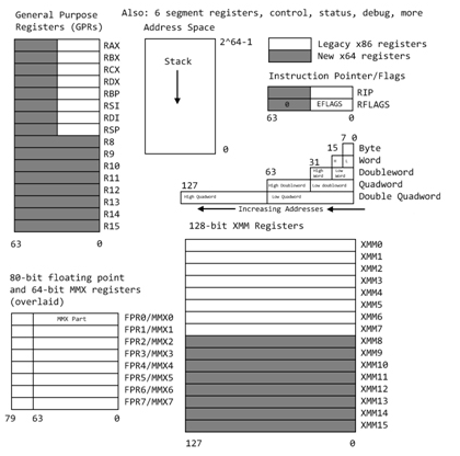
The Intel x86-64 has many registers and named sub-registers.
This is why your 16-bit Intel programs will still run.
Here are some that are used in assembly language programming
and debugging (the "dash number" gives the number of bits):
Typically typed lower case.
+---------------------------------+ A register
|RAX-64 |
| +---------------------------+| RAX really extended accumulator
| | EAX-32 +-----------------+|| EAX extended extended accumulator
| | | AX-16 ||| Ax extended accumulator
| | |+--------+------+||| (A multiplicand before multiply)
| | || AH-8 | AL-8 |||| (A lower part of dividend before divide)
| | |+--------+------+||| (A lower part of product)
| | +-----------------+|| (H for high, L for low byte)
| +---------------------------+|
+---------------------------------+
+---------------------------------+ B register
|RBX-64 |
| +---------------------------+| RBX really extended base pointer
| | EBX-32 +-----------------+|| (EBX is double word segment)
| | | BX-16 ||| (BX is word segment)
| | |+--------+------+|||
| | || BH-8 | BL-8 ||||
| | |+--------+------+|||
| | +-----------------+||
| +---------------------------+|
+---------------------------------+
+---------------------------------+ C register
|RCX-64 |
| +---------------------------+| RCX 64-bit counter
| | ECX-32 +-----------------+|| (string and loop operations)
| | | CX-16 ||| (ECX is a 32 bit counter)
| | |+--------+------+||| (CX is a 16 bit counter)
| | || CH-8 | CL-8 |||| (see loop instruction)
| | |+--------+------+|||
| | +-----------------+||
| +---------------------------+|
+---------------------------------+
+---------------------------------+ D register
|RDX-64 |
| +---------------------------+| RDX extended EDX extended DX
| | EDX-32 +-----------------+|| (I/O pointer for memory mapped I/O)
| | | DX-16 ||| (D remainder after divide)
| | |+--------+------+||| (D upper part of dividend)
| | || DH-8 | DL-8 |||| (D upper part of product)
| | |+--------+------+|||
| | +-----------------+||
| +---------------------------+|
+---------------------------------+
+---------------------------------+ Stack Pointer
|RSP-64 |
| +---------------------------+| RSP 64-bit stack pointer
| | ESP-32 +-------------+|| ESP extended stack pointer
| | | SP-16 ||| SP stack pointer
| | +-------------+|| (used by PUSH and POP)
| +---------------------------+|
+---------------------------------+
+---------------------------------+ Base Pointer
|RBP-64 |
| +---------------------------+| RBP 64-bit base pointer
| | EBP-32 +-------------+|| EBP extended base pointer
| | | BP-16 ||| (by convention, callers stack)
| | +-------------+|| (BP in ES segment)
| +---------------------------+| We save it, push then pop
+---------------------------------+
+---------------------------------+ Source Index
|RSI-64 |
| +---------------------------+| RSI 64-bit source index
| | ESI-32 +-------------+|| ESI extended source index
| | | SI-16 ||| SI source index
| | +-------------+|| (SI in DS segment)
| +---------------------------+|
+---------------------------------+
+---------------------------------+ Destination Index
|RDI-64 |
| +---------------------------+| RDI 64-bit destination index
| | EDI-32 +-------------+|| EDI extended destination index
| | | DI-16 ||| DI destination index
| | +-------------+|| (DI in ES segment)
| +---------------------------+|
+---------------------------------+
+---------------------------------+ Instruction Pointer
|RIP-64 |
| +---------------------------+| RIP 64-bit instruction pointer
| | EIP-32 +-------------+|| EIP extended instruction pointer
| | | IP-16 ||| IP instruction pointer
| | +-------------+|| set by jump and call
| +---------------------------+|
+---------------------------------+
+---------------------------------+ Flags indicating errors
|RFLAGS-64 |
| +---------------------------+| RFLAGS 64-bit flags
| | EFLAGS-32 +-------------+|| EFLAGS extended flags
| | | FLAGS-16 ||| FLAGS
| | +-------------+|| (not a register name!)
| +---------------------------+| (must use PUSHF and POPF)
+---------------------------------+
Additional 64-bit registers are R8, R9, R10, R11, R12, R13, R14, R15
128-bit Registers for SSE instructions and printf are xmm0, ..., xmm15
Additional floating point stack, fld, fst, fstp, st0, st1, ... 80 bit
Use of registers and little endian
see testreg_64.asm for register syntax
see testreg_64.lst for binary encoding
Just a snippet of testreg_64.asm :
section .data ; preset constants, writeable
aa8: db 8 ; 8-bit
aa16: dw 16 ; 16-bit
aa32: dd 32 ; 32-bit
aa64: dq 64 ; 64-bit
section .text ; instructions, code segment
mov rax,[aa64] ; five registers in RAX
mov eax,[aa32] ; four registers in EAX
mov ax,[aa16]
mov ah,[aa8]
mov al,[aa8]
Just a snippet of testreg_64.lst
(line number, hex address in segment, hex data, assembly language)
((note byte 10 hex is 16 decimal, 20 hex is 32 decimal, etc))
((( note little endian, least significant byte first.)))
8 00000000 08 aa8: db 8
9 00000001 1000 aa16: dw 16
10 00000003 20000000 aa32: dd 32
11 00000007 4000000000000000 aa64: dq 64
24 00000001 488B0425[07000000] mov rax,[aa64]
25 00000009 8B0425[03000000] mov eax,[aa32]
26 00000010 668B0425[01000000] mov ax,[aa16]
27 00000018 8A2425[00000000] mov ah,[aa8]
28 0000001F 8A0425[00000000] mov al,[aa8]
OH! Did I forget to mention that Intel is a "little endian" machine.
The bytes are stored backwards to English.
The little end, least significant byte is first, smallest address.
Other registers that are extended include:
+-------------+ CS code segment
| CS-16 |
+-------------+
+-------------+ SS stack segment
| SS-16 |
+-------------+
+-------------+ DS data segment
| DS-16 | (current module)
+-------------+
+-------------+ ES data segment
| ES-16 | (calling module, destination string)
+-------------+
+-------------+ FS heap segment
| FS-16 |
+-------------+
+-------------+ GS global segment
| GS-16 | (shared)
+-------------+
There are also 80-bit or more, floating point registers ST0, ..., ST7
(These are actually a stack, note FST vs FSTP etc)
There are also control registers CR0, ..., CR4
There are also debug registers DR0, DR1, DR2, DR3, DR6, DR7
There are also test registers TR3, ...., TR7
Basic NASM syntax
The basic syntax for a line in NASM is:
label: opcode operand(s) ; comment
The "label" is a case sensitive user name, followed by a colon.
The label is optional and when not present, indent the opcode.
The label should start in column one of the line.
The label may be on a line with nothing else or a comment.
In assembly language the "label" is an address,
not a value as it is in compiler language.
The "opcode" is not case sensitive and may be a machine instruction
or an assembler directive (pseudo operation) or a macro call.
Typically, all "opcode" fields are neatly lined up starting in the
same column. Use of "tab" is OK.
Machine instructions may be preceded by a "prefix" such as:
a16, a32, o16, o32, and others.
"operand(s)" depend on the choice of "opcode".
An operand may have several parts separated by commas,
The parts may be a combination of register names, constants,
memory references in brackets [ ] or empty.
Comments are optional, yet encouraged.
Everything from the semicolon to the end of the line is
a comment, ignored by the assembler.
The semicolon may be in column one, making the entire line
a comment. Some editors put in two semicolon, no difference.
Sections or segments:
One specific assembler directive is the "section" or "SECTION"
directive. Four types of section are predefined for ELF format:
section .data ; initialized data
; writeable, not executable
; default alignment 8 bytes
section .bss ; uninitialized space for data
; writeable, not executable
; default alignment 8 bytes
section .rodata ; initialized data
; read only, not executable
; default alignment 8 bytes
section .text ; instructions (code)
; not writeable, executable
; default alignment 16 bytes
section other ; any name other than .data, .bss,
; .rodata, .text
; your stuff
; not executable, not writeable
; default alignment 1 byte
Efficiency and samples
A few comments on efficiency:
My experience is that a good assembly language programmer
can make a small (about 100 lines) "C" program more
efficient than the gcc compiler. But, for larger
programs, the compiler will be more efficient.
Exceptions are, for example, the SGI IRIX cc compiler
that has super optimization for that specific machine.
For the Intel x86-64 here are some samples in nasm and from gcc
(different syntax but you should be able to recognize the instructions)
Focus on the loop, there is prologue and epilogue code that should
be included, yet was omitted. Note the test has "check" values
at each end of the array. There is no range testing in
either "C" or assembly language.
A simple loop loopint_64.asm
; loopint_64.asm code loopint.c for nasm
; /* loopint_64.c a very simple loop that will be coded for nasm */
; #include <stdio.h>
; int main()
; {
; long int dd1[100]; // 100 could be 3 gigabytes
; long int i; // must be long for more than 2 gigabytes
; dd1[0]=5; /* be sure loop stays 1..98 */
; dd1[99]=9;
; for(i=1; i<99; i++) dd1[i]=7;
; printf("dd1[0]=%ld, dd1[1]=%ld, dd1[98]=%ld, dd1[99]=%ld\n",
; dd1[0], dd1[1], dd1[98],dd1[99]);
; return 0;
;}
; execution output is dd1[0]=5, dd1[1]=7, dd1[98]=7, dd1[99]=9
section .bss
dd1: resq 100 ; reserve 100 long int
i: resq 1 ; actually unused, kept in register
section .data ; Data section, initialized variables
fmt: db "dd1[0]=%ld, dd1[1]=%ld, dd1[98]=%ld, dd1[99]=%ld",10,0
extern printf ; the C function, to be called
section .text
global main
main: push rbp ; set up stack
mov qword [dd1],5 ; dd1[0]=5; memory to memory
mov qword [dd1+99*8],9 ; dd1[99]=9; indexed 99 qword
mov rdi, 1*8 ; i=1; index, will move by 8 bytes
loop1: mov qword [dd1+rdi],7 ; dd1[i]=7;
add rdi, 8 ; i++; 8 bytes
cmp rdi, 8*99 ; i<99
jne loop1 ; loop until incremented i=99
mov rdi, fmt ; pass address of format
mov rsi, qword [dd1] ; dd1[0] first list parameter
mov rdx, qword [dd1+1*8] ; dd1[1] second list parameter
mov rcx, qword [dd1+98*8] ; dd1[98] third list parameter
mov r8, qword [dd1+99*8] ; dd1[99] fourth list parameter
mov rax, 0 ; no xmm used
call printf ; Call C function
pop rbp ; restore stack
mov rax,0 ; normal, no error, return value
ret ; return
The simplest loop in NASM requires use of register rcx
"C" for(j=n; j>0; j--) // count down from n, do not use j==0
{
a[j] = 0.0;
}
section .data
n: dq 9
zero: dq 0.0
section .bss
a: resq 9
section .text
mov rcx, [n] ; j = 9; // start loop
jlab: fld qword [zero]
fstp qword [a+8*rcx] ; a[j] = 0.0; each a is 8 bytes
loop jlab ; j=j-1, jump to jlab: if j>0
A loop that counts up requires you to do the increment and compare:
"C" for(j=0; j<n; j++) // count up from zero, do not use j==n
{
a[j] = 0.0;
}
section .data
n: dq 9
zero: dq 0.0
section .bss
a: resq 9
section .text
mov rax,0 ; j = 0; // start loop
jlab: fld qword [zero]
fstp qword [a+8*rax] ; a[j] = 0.0; each a is 8 bytes
inc rax ; j = j + 1
cmp rax,[n] ; j <n ?
jl jlab ; jump to jlab: if j<n
Speed consideration must take into account cache and virtual memory
performance, number of bytes transferred from RAM and clock cycles.
On modern computer architectures, this is almost impossible. For example,
the Pentium 4 translates the 80x86 code into RISC pipeline code and
is actually executing instructions that are different from the
assembly language. Carefully benchmarking complete applications is
about the only conclusive measure of efficiency.
"C" and other programming languages may call subroutines, functions,
procedures written in assembly language. Here is a small sample
using floating point just to show use of ST registers, mentioned in comments.
Main C program test_callf1_64.c
callf1_64.h
// test_callf1_64.c test callf1_64.asm
// nasm -f elf64 -l callf1_64.lst callf1_64.asm
// gcc -m64 -o test_callf1_64 test_callf1_64.c callf1_64.o
// ./test_callf1_64 > test_callf1_64.out
#include "callf1_64.h"
#include <stdio.h>
int main()
{
double L[2];
printf("test_callf1_64.c using callf1_64.asm\n");
L[0]=1.0;
L[1]=2.0;
callf1_64(L); // add 3.0 to L[0], add 4.0 to L[1]
printf("L[0]=%e, L[1]=%e \n", L[0], L[1]);
return 0;
}
Full with debug callf1_64.asm
Stripped down callf1_64.asm with no demo, no debug:
; callf1_64.asm a basic structure for a subroutine to be called from "C"
; Parameter: double *L
; Result: L[0]=L[0]+3.0 L[1]=L[1]+4.0
global callf1_64 ; linker must know name of subroutine
SECTION .data ; Data section, initialized variables
a3: dq 3.0 ; 64-bit variable a initialized to 3.0
a4: dq 4.0 ; 64-bit variable b initializes to 4.0
SECTION .text ; Code section.
callf1_64: ; name must appear as a nasm label
push rbp ; save rbp
mov rax,rdi ; first, only, in parameter, address
; add 3.0 to L[0]
fld qword [rax] ; load L[0] (pushed on flt pt stack, st0)
fadd qword [a3] ; floating add 3.0 (to st0)
fstp qword [rax] ; store into L[0] (pop flt pt stack)
fld qword [rax+8] ; load L[1] (pushed on flt pt stack, st0)
fadd qword [a4] ; floating add 4.0 (to st0)
fstp qword [rax+8] ; store into L[1] (pop flt pt stack)
pop rbp ; restore callers stack frame
ret ; return
We did not need to save floating point stack, we left it unchanged.
We could have used dt and tword for 80 bit floating point.
Calling printf uses xmm registers.
Simple loop using register rcx
loop_64.asm
loop_64_asm.out
; loop_64.asm simple using rcx and loop
; for(i=9; i>0; i++) A[i] = 0;
; Assemble: nasm -f elf64 loop_64.asm
; Link: gcc -m64 -o loop_64 loop_64.o
; Run: ./loop_64 > loop_64.out
; Output: cat hello_64.out
extern printf ; the C function, to be called
section .data ; Data section, initialized variables
fmt: db "A[%ld]=0", 10, 0 ; The printf format, "\n",'0'
section .bss
A: resq 10 ; A[0] .. A[9] in C A[0] unused
sav: resq 1 ; in case printf clobbers rcx
section .text ; Code section.
global main ; the standard gcc entry point
main: ; the program label for the entry point
push rbp ; set up stack frame, must be aligned
mov rcx,9
loop1: mov qword [A+rcx*8],0 ; A[i] = 0
mov [sav],rcx ; printf clobbers rcx debug printout
mov rdi,fmt ; address of format, standard register rdi
mov rsi,rcx ; address of first data, standard register rsi
mov rax,0 ; no float or double in xmm
call printf ; Call C function
mov rcx,[sav]
loop loop1 ; decrement rcx, jump if rcx > 0 zero
; [A+rcx*8-8] A[8] .. A[0]
pop rbp ; restore stack
mov rax,0 ; normal, no error, return value
ret ; return
output in loop_64_asm.out with -8 could be A[8]=0 .. A[0]=0
A[9]=0
A[8]=0
A[7]=0
A[6]=0
A[5]=0
A[4]=0
A[3]=0
A[2]=0
A[1]=0
A bunch of information, much you do not need, on nasm
nasmh.txt from nasm -h
Both integer and floating point arithmetic are demonstrated.
In order to make the source code smaller, a macro is defined
to print out results. The equivalent "C" program is given as
comments.

First, see how to call the "C" library function, printf, to make
it easier to print values:
Look at the file printf1_64.asm

; printf1_64.asm   print an integer from storage and from a register
; Assemble:	nasm -f elf64 -l printf1_64.lst  printf1_64.asm
; Link:		gcc -m64 -o printf1_64  printf1_64.o
; Run:		./printf1_64 > printf1_64.out
; Output:	a=5, rax=7

; Equivalent C code
; /* printf1.c  print a long int, 64-bit, and an expression */
; #include <stdio.h>
; int main()
; {
;   long int a=5;
;   printf("a=%ld, rax=%ld\n", a, a+2);
;   return 0;
; }

; Declare external function
        extern	printf		; the C function, to be called

        SECTION .data		; Data section, initialized variables

	a:	dq	5	; long int a=5;
fmt:    db "a=%ld, rax=%ld", 10, 0	; The printf format, "\n",'0'


        SECTION .text           ; Code section.

        global main		; the standard gcc entry point
main:				; the program label for the entry point
        push    rbp		; set up stack frame

	mov	rax,[a]		; put "a" from store into register
	add	rax,2		; a+2  add constant 2
	mov	rdi,fmt		; format for printf
	mov	rsi,[a]         ; first parameter for printf
	mov	rdx,rax         ; second parameter for printf
	mov	rax,0		; no xmm registers
        call    printf		; Call C function

	pop	rbp		; restore stack

	mov	rax,0		; normal, no error, return value
	ret			; return

Printing floating point
Now, we may need to print "float" and "double" and calling  printf
gets more complicated. Still easier than doing your own conversion.
Look at the file printf2.asm
Output is printf2.out

; printf2_64.asm  use "C" printf on char, string, int, long int, float, double
;
; Assemble:	nasm -f elf64 -l printf2_64.lst  printf2_64.asm
; Link:		gcc -m64 -o printf2_64  printf2_64.o
; Run:		./printf2_64 > printf2_64.out
; Output:	cat printf2_64.out
;
; A similar "C" program   printf2_64.c
; #include <stdio.h>
; int main()
; {
;   char      char1='a';            /* sample character */
;   char      str1[]="mystring";    /* sample string */
;   int       len=9;                /* sample string */
;   int       inta1=12345678;       /* sample integer 32-bit */
;   long int  inta2=12345678900;    /* sample long integer 64-bit */
;   long int  hex1=0x123456789ABCD; /* sample hexadecimal 64-bit*/
;   float     flt1=5.327e-30;       /* sample float 32-bit */
;   double    flt2=-123.4e300;      /* sample double 64-bit*/
;
;   printf("printf2_64: flt2=%e\n", flt2);
;   printf("char1=%c, srt1=%s, len=%d\n", char1, str1, len);
;   printf("char1=%c, srt1=%s, len=%d, inta1=%d, inta2=%ld\n",
;          char1, str1, len, inta1, inta2);
;   printf("hex1=%lX, flt1=%e, flt2=%e\n", hex1, flt1, flt2);
;   return 0;
; }
        extern printf                   ; the C function to be called

        SECTION .data                   ; Data section
					; format strings for printf
fmt2:   db "printf2: flt2=%e", 10, 0
fmt3:	db "char1=%c, str1=%s, len=%d", 10, 0
fmt4:	db "char1=%c, str1=%s, len=%d, inta1=%d, inta2=%ld", 10, 0
fmt5:	db "hex1=%lX, flt1=%e, flt2=%e", 10, 0

char1:	db	'a'			; a character
str1:	db	"mystring",0	        ; a C string, "string" needs 0
len:	equ	$-str1			; len has value, not an address
inta1:	dd	12345678		; integer 12345678, note dd
inta2:	dq	12345678900		; long integer 12345678900, note dq
hex1:	dq	0x123456789ABCD	        ; long hex constant, note dq
flt1:	dd	5.327e-30		; 32-bit floating point, note dd
flt2:	dq	-123.456789e300	        ; 64-bit floating point, note dq

	SECTION .bss

flttmp:	resq 1			        ; 64-bit temporary for printing flt1

        SECTION .text                   ; Code section.

        global	main		        ; "C" main program
main:				        ; label, start of main program
	push    rbp			; set up stack frame
	fld	dword [flt1]	        ; need to convert 32-bit to 64-bit
	fstp	qword [flttmp]          ; floating load makes 80-bit,
	                                ; store as 64-bit
	mov	rdi,fmt2
	movq	xmm0, qword [flt2]
	mov	rax, 1			; 1 xmm register
	call	printf

	mov	rdi, fmt3		; first arg, format
	mov	rsi, [char1]		; second arg, char
	mov	rdx, str1		; third arg, string
	mov	rcx, len		; fourth arg, int
	mov	rax, 0			; no xmm used
	call	printf

	mov	rdi, fmt4		; first arg, format
	mov	rsi, [char1]		; second arg, char
	mov	rdx, str1		; third arg, string
	mov	rcx, len		; fourth arg, int
	mov	r8, [inta1]		; fifth arg, inta1 32->64
	mov	r9, [inta2]		; sixth arg, inta2
	mov	rax, 0			; no xmm used
	call	printf

	mov	rdi, fmt5		; first arg, format
	mov	rsi, [hex1]		; second arg, char
	movq	xmm0, qword [flttmp]    ; first double
	movq	xmm1, qword [flt2]	; second double
	mov	rax, 2			; 2 xmm used
	call	printf

	pop	rbp			; restore stack
        mov     rax, 0			; exit code, 0=normal
        ret				; main returns to operating system


Integer arithmetic
Now, for integer arithmetic, look at the file intarith_64.asm
Output is intarith_64.out
C version is intarith_64.c
Since all the lines use the same format, a macro was created
to do the call on printf.

; intarith_64.asm    show some simple C code and corresponding nasm code
;                    the nasm code is one sample, not unique
;
; compile:	nasm -f elf64 -l intarith_64.lst  intarith_64.asm
; link:		gcc -m64 -o intarith_64  intarith_64.o
; run:		./intarith_64 > intarith_64.out
;
; the output from running intarith.c is:
; c=5  , a=3, b=4, c=5
; c=a+b, a=3, b=4, c=7
; c=a-b, a=3, b=4, c=-1
; c=a*b, a=3, b=4, c=12
; c=c/a, a=3, b=4, c=4
;
;The file  intarith.c  is:
;  /* intarith.c */
;  #include <stdio.h>
;  int main()
;  {
;    long int a=3, b=4, c;
;    c=5;
;    printf("%s, a=%ld, b=%ld, c=%ld\n","c=5  ", a, b, c);
;    c=a+b;
;    printf("%s, a=%ld, b=%ld, c=%ld\n","c=a+b", a, b, c);
;    c=a-b;
;    printf("%s, a=%ld, b=%ld, c=%ld\n","c=a-b", a, b, c);
;    c=a*b;
;    printf("%s, a=%ld, b=%ld, c=%ld\n","c=a*b", a, b, c);
;    c=c/a;
;    printf("%s, a=%ld, b=%ld, c=%ld\n","c=c/a", a, b, c);
;    return 0;
; }
        extern printf		; the C function to be called

%macro	pabc 1			; a "simple" print macro
	section .data
.str	db	%1,0		; %1 is first actual in macro call
	section .text
        mov     rdi, fmt4	; first arg, format
	mov	rsi, .str	; second arg
	mov     rdx, [a]        ; third arg
	mov     rcx, [b]        ; fourth arg
	mov     r8, [c]         ; fifth arg
	mov     rax, 0	        ; no xmm used
	call    printf		; Call C function
%endmacro

	section .data  		; preset constants, writeable
a:	dq	3		; 64-bit variable a initialized to 3
b:	dq	4		; 64-bit variable b initializes to 4
fmt4:	db "%s, a=%ld, b=%ld, c=%ld",10,0	; format string for printf

	section .bss 		; unitialized space
c:	resq	1		; reserve a 64-bit word

	section .text		; instructions, code segment
	global	 main		; for gcc standard linking
main:				; label
	push 	rbp		; set up stack
lit5:				; c=5;
	mov	rax,5	 	; 5 is a literal constant
	mov	[c],rax		; store into c
	pabc	"c=5  "		; invoke the print macro

addb:				; c=a+b;
	mov	rax,[a]	 	; load a
	add	rax,[b]		; add b
	mov	[c],rax		; store into c
	pabc	"c=a+b"		; invoke the print macro

subb:				; c=a-b;
	mov	rax,[a]	 	; load a
	sub	rax,[b]		; subtract b
	mov	[c],rax		; store into c
	pabc	"c=a-b"		; invoke the print macro

mulb:				; c=a*b;
	mov	rax,[a]	 	; load a (must be rax for multiply)
	imul	qword [b]	; signed integer multiply by b
	mov	[c],rax		; store bottom half of product into c
	pabc	"c=a*b"		; invoke the print macro

mulcx:				; c=b*b rcx;
	mov	rcx,[b]	 	; load b into rcx
	imul	rcx,[b]	        ; signed integer multiply by b
	mov	[c],rcx		; store bottom half of product into c
	pabc	"c=b*b rcx"	; invoke the print macro

mulbn:				; c=a*b;
	mov	rax,[a]	 	; load a (must be rax for multiply)
	mul	qword [b]	; signed integer multiply by b
	mov	[c],rax		; store bottom half of product into c
	pabc	"c=a*b mul"	; invoke the print macro

diva:				; c=c/a;   both idiv and div allowed
	mov	rax,[c]	 	; load c
	mov	rdx,0		; load upper half of dividend with zero
	idiv	qword [a]	; divide double register rdx rax by a
	mov	[c],rax		; store quotient into c
	pabc	"c=c/a"		; invoke the print macro

anda:
	mov	rax,[a]	 	; load a
	and	rax,1	        ; logical and, bottom bit
	mov	[c],rax		; store result, just botton bit
	pabc	"c=a and 1 "	; invoke the print macro
				; also available "or" "xor" "not"
shrb:
	mov	rax,[b]	 	; load b
	shr	rax,1	        ; shift bits right 1 place
	mov	[c],rax		; store result, botton bit gone
	pabc	"c=b shr 1 "	; invoke the print macro

	pop	rbp		; pop stack
        mov     rax,0           ; exit code, 0=normal
	ret			; main returns to operating system

Output running intarith_64.asm is:

c=5  , a=3, b=4, c=5
c=a+b, a=3, b=4, c=7
c=a-b, a=3, b=4, c=-1
c=a*b, a=3, b=4, c=12
c=b*b rcx, a=3, b=4, c=16
c=a*b mul, a=3, b=4, c=12
c=c/a, a=3, b=4, c=4
c=a and 1 , a=3, b=4, c=1
c=b shr 1 , a=3, b=4, c=2


Note that two registers are used for general multiply and divide.

        bbbb  [mem] a product of 64-bits times 64-bits is 128-bits
 imul   bbbb  rax
   ---------
rdx bbbbbbbb  rax   the upper part of the product is in rdx
                    the lower part of the product is in rax


rdx bbbbbbbb  rax  before divide, the upper part of dividend is in rdx
                                  the lower part of dividend is in rax
 idiv   bbbb  [mem] the divisor
    --------
                   after divide,  the quotient is in rax
                                  the remainder is in rdx

Floating point arithmetic
Now, for floating point arithmetic, look at the file fltarith_64.asm
Output is fltarith_64.out
C version is fltarith_64.c
Since all the lines use the same format, a macro was created
to do the call on printf.

Note the many similarities to integer arithmetic, yet some basic differences.

; fltarith_64.asm   show some simple C code and corresponding nasm code
;                   the nasm code is one sample, not unique
;
; compile  nasm -f elf64 -l fltarith_64.lst  fltarith_64.asm
; link     gcc -m64 -o fltarith_64  fltarith_64.o
; run      ./fltarith_64 > fltarith_64.out
;
; the output from running fltarith and fltarithc is:
; c=5.0, a=3.000000e+00, b=4.000000e+00, c=5.000000e+00
; c=a+b, a=3.000000e+00, b=4.000000e+00, c=7.000000e+00
; c=a-b, a=3.000000e+00, b=4.000000e+00, c=-1.000000e+00
; c=a*b, a=3.000000e+00, b=4.000000e+00, c=1.200000e+01
; c=c/a, a=3.000000e+00, b=4.000000e+00, c=4.000000e+00
; a=i  , a=8.000000e+00, b=1.600000e+01, c=1.600000e+01
; a<=b , a=8.000000e+00, b=1.600000e+01, c=1.600000e+01
; b==c , a=8.000000e+00, b=1.600000e+01, c=1.600000e+01
;The file  fltarith.c  is:
;  #include <stdio.h>
;  int main()
;  {
;    double a=3.0, b=4.0, c;
;    long int i=8;
;
;    c=5.0;
;    printf("%s, a=%e, b=%e, c=%e\n","c=5.0", a, b, c);
;    c=a+b;
;    printf("%s, a=%e, b=%e, c=%e\n","c=a+b", a, b, c);
;    c=a-b;
;    printf("%s, a=%e, b=%e, c=%e\n","c=a-b", a, b, c);
;    c=a*b;
;    printf("%s, a=%e, b=%e, c=%e\n","c=a*b", a, b, c);
;    c=c/a;
;    printf("%s, a=%e, b=%e, c=%e\n","c=c/a", a, b, c);
;    a=i;
;    b=a+i;
;    i=b;
;    c=i;
;    printf("%s, a=%e, b=%e, c=%e\n","c=c/a", a, b, c);
;    if(a<b) printf("%s, a=%e, b=%e, c=%e\n","a<=b ", a, b, c);
;    else    printf("%s, a=%e, b=%e, c=%e\n","a>b  ", a, b, c);
;    if(b==c)printf("%s, a=%e, b=%e, c=%e\n","b==c ", a, b, c);
;    else    printf("%s, a=%e, b=%e, c=%e\n","b!=c ", a, b, c);
;    return 0;
; }

        extern printf		; the C function to be called

%macro	pabc 1			; a "simple" print macro
	section	.data
.str	db	%1,0		; %1 is macro call first actual parameter
	section .text
				; push onto stack backwards
        mov	rdi, fmt	; address of format string
	mov	rsi, .str	; string passed to macro
	movq	xmm0, qword [a]	; first floating point in fmt
	movq	xmm1, qword [b]	; second floating point
	movq	xmm2, qword [c]	; third floating point
	mov	rax, 3		; 3 floating point arguments to printf
        call    printf          ; Call C function
%endmacro

	section	.data  		; preset constants, writeable
a:	dq	3.0		; 64-bit variable a initialized to 3.0
b:	dq	4.0		; 64-bit variable b initializes to 4.0
i:	dq	8		; a 64 bit integer
five:	dq	5.0		; constant 5.0
fmt:    db "%s, a=%e, b=%e, c=%e",10,0	; format string for printf

	section .bss 		; unitialized space
c:	resq	1		; reserve a 64-bit word

	section .text		; instructions, code segment
	global	main		; for gcc standard linking
main:				; label

	push	rbp		; set up stack
lit5:				; c=5.0;
	fld	qword [five]	; 5.0 constant
	fstp	qword [c]	; store into c
	pabc	"c=5.0"		; invoke the print macro

addb:				; c=a+b;
	fld	qword [a] 	; load a (pushed on flt pt stack, st0)
	fadd	qword [b]	; floating add b (to st0)
	fstp	qword [c]	; store into c (pop flt pt stack)
	pabc	"c=a+b"		; invoke the print macro

subb:				; c=a-b;
	fld	qword [a] 	; load a (pushed on flt pt stack, st0)
	fsub	qword [b]	; floating subtract b (to st0)
	fstp	qword [c]	; store into c (pop flt pt stack)
	pabc	"c=a-b"		; invoke the print macro

mulb:				; c=a*b;
	fld	qword [a]	; load a (pushed on flt pt stack, st0)
	fmul	qword [b]	; floating multiply by b (to st0)
	fstp	qword [c]	; store product into c (pop flt pt stack)
	pabc	"c=a*b"		; invoke the print macro

diva:				; c=c/a;
	fld	qword [c] 	; load c (pushed on flt pt stack, st0)
	fdiv	qword [a]	; floating divide by a (to st0)
	fstp	qword [c]	; store quotient into c (pop flt pt stack)
	pabc	"c=c/a"		; invoke the print macro

intflt:				; a=i;
	fild	qword [i]	; load integer as floating point
	fst	qword [a]	; store the floating point (no pop)
	fadd	st0		; b=a+i; 'a' as 'i'  already on flt stack
	fst	qword [b]	; store sum (no pop) 'b' still on stack
	fistp	qword [i]	; i=b; store floating point as integer
	fild	qword [i]	; c=i; load again from ram (redundant)
	fstp	qword [c]
	pabc	"a=i  "		; invoke the print macro

cmpflt:	fld	qword [b]	; into st0, then pushed to st1
	fld	qword [a]	; in st0
	fcomip	st0,st1		; a compare b, pop a
	jg	cmpfl2
	pabc	"a<=b "
	jmp	cmpfl3
cmpfl2:
	pabc	"a>b  "
cmpfl3:
	fld	qword [c]	; should equal [b]
	fcomip  st0,st1
	jne	cmpfl4
	pabc	"b==c "
	jmp	cmpfl5
cmpfl4:
	pabc	"b!=c "
cmpfl5:

	pop	rbp		; pop stack
        mov     rax,0           ; exit code, 0=normal
	ret			; main returns to operating system

Shift data in a register
Refer to nasmdoc.txt for details.
A brief summary is provided here.
"reg" is an 8-bit, 16-bit or 32-bit or 64-bit register
"count" is a number of bits to shift
"right" moves contents of the register to the right, makes it smaller
"left" moves contents of the register to the left, makes it bigger

  SAL   reg,count   shift arithmetic left
  SAR   reg,count   shift arithmetic right (sign extension)
  SHL   reg,count   shift left (logical, zero fill)
  SHR   reg,count   shift right (logical, zero fill)
  ROL   reg,count   rotate left
  ROR   reg,count   rotate right
  SHLD  reg1,reg2,count  shift left double-register
  SHRD  reg1,reg2,count  shift right double-register

An example of using the various shifts is in: shift_64.asm
Output is shift_64.out
Just to make it easy to check, we keep all shift amounts a multiple
of 4, 4 bits per hex digit in output.

; shift_64.asm    the nasm code is one sample, not unique
;
; compile:	nasm -f elf64 -l shift_64.lst  shift_64.asm
; link:		gcc -m64 -o shift_64  shift_64.o
; run:		./shift_64 > shift_64.out
;
; the output from running shift.asm (zero filled) is:
; shl rax,4, old rax=ABCDEF0987654321, new rax=BCDEF09876543210,
; shl rax,8, old rax=ABCDEF0987654321, new rax=CDEF098765432100,
; shr rax,4, old rax=ABCDEF0987654321, new rax= ABCDEF098765432,
; sal rax,8, old rax=ABCDEF0987654321, new rax=CDEF098765432100,
; sar rax,4, old rax=ABCDEF0987654321, new rax=FABCDEF098765432,
; rol rax,4, old rax=ABCDEF0987654321, new rax=BCDEF0987654321A,
; ror rax,4, old rax=ABCDEF0987654321, new rax=1ABCDEF098765432,
; shld rdx,rax,8, old rdx:rax=0,ABCDEF0987654321,
;                 new rax=ABCDEF0987654321 rdx=              AB,
; shl rax,8     , old rdx:rax=0,ABCDEF0987654321,
;                 new rax=CDEF098765432100 rdx=              AB,
; shrd rdx,rax,8, old rdx:rax=0,ABCDEF0987654321,
;                 new rax=ABCDEF0987654321 rdx=2100000000000000,
; shr rax,8     , old rdx:rax=0,ABCDEF0987654321,
;                 new rax=  ABCDEF09876543 rdx=2100000000000000,

        extern printf		; the C function to be called

%macro	prt	1		; old and new rax
	section .data
.str	db	%1,0		; %1 is which shift string
	section .text
        mov	rdi, fmt	; address of format string
	mov	rsi, .str 	; callers string
	mov	rdx,rax		; new value
	mov	rax, 0		; no floating point
        call    printf          ; Call C function
%endmacro

%macro	prt2	1		; old and new rax,rdx
	section .data
.str	db	%1,0		; %1 is which shift
	section .text
        mov	rdi, fmt2	; address of format string
	mov	rsi, .str 	; callers string
	mov	rcx, rdx	; new rdx befor next because used
	mov	rdx, rax	; new rax
	mov	rax, 0		; no floating point
        call    printf          ; Call C function
%endmacro

	 section .bss
raxsave: resq	1		; save rax while calling a function
rdxsave: resq	1		; save rdx while calling a function

	section .data  		; preset constants, writeable
b64:	dq	0xABCDEF0987654321	; data to shift
fmt:    db "%s, old rax=ABCDEF0987654321, new rax=%16lX, ",10,0	; format string
fmt2:   db "%s, old rdx:rax=0,ABCDEF0987654321,",10,"                new rax=%16lX rdx=%16lX, ",10,0

	section .text		; instructions, code segment
	global	 main		; for gcc standard linking
main:	push	rbp		; set up stack

shl1:	mov	rax, [b64]	; data to shift
	shl	rax, 4		; shift rax 4 bits, one hex position left
	prt	"shl rax,4 "	; invoke the print macro

shl4:	mov	rax, [b64]	; data to shift
	shl	rax,8		; shift rax 8 bits. two hex positions left
	prt	"shl rax,8 "	; invoke the print macro

shr4:	mov	rax, [b64]	; data to shift
	shr	rax,4		; shift
	prt	"shr rax,4 "	; invoke the print macro

sal4:	mov	rax, [b64]	; data to shift
	sal	rax,8		; shift
	prt	"sal rax,8 "	; invoke the print macro

sar4:	mov	rax, [b64]	; data to shift
	sar	rax,4		; shift
	prt	"sar rax,4 "	; invoke the print macro

rol4:	mov	rax, [b64]	; data to shift
	rol	rax,4		; shift
	prt	"rol rax,4 "	; invoke the print macro

ror4:	mov	rax, [b64]	; data to shift
	ror	rax,4		; shift
	prt	"ror rax,4 "	; invoke the print macro

shld4:	mov	rax, [b64]	; data to shift
	mov	rdx,0		; register receiving bits
	shld	rdx,rax,8	; shift
	mov	[raxsave],rax	; save, destroyed by function
	mov	[rdxsave],rdx	; save, destroyed by function
	prt2	"shld rdx,rax,8"; invoke the print macro

shla:	mov	rax,[raxsave]	; restore, destroyed by function
	mov	rdx,[rdxsave]	; restore, destroyed by function
	shl	rax,8		; finish double shift, both registers
	prt2	"shl rax,8     "; invoke the print macro

shrd4:	mov	rax, [b64]	; data to shift
	mov	rdx,0		; register receiving bits
	shrd	rdx,rax,8	; shift
	mov	[raxsave],rax	; save, destroyed by function
	mov	[rdxsave],rdx	; save, destroyed by function
	prt2	"shrd rdx,rax,8"; invoke the print macro

shra:	mov	rax,[raxsave]	; restore, destroyed by function
	mov	rdx,[rdxsave]	; restore, destroyed by function
	shr	rax,8		; finish double shift, both registers
	prt2	"shr rax,8     "; invoke the print macro

	pop	rbp		; restore stack
	mov     rax,0           ; exit code, 0=normal
	ret			; main returns to operating system

First project is assigned.
You may want to wait until the next lecture and do HW3 before
starting the project. Code and debug your first Nasm program.
www.cs.umbc.edu/~squire/cs313_proj.shtml
See www.csee.umbc.edu/help/nasm/nasm_64.shtml for notes on using debugger.
A program that prints where its sections are allocated
(in virtual memory) is where_64.asm
My output, yours should be different, is
where_64.lst
where_64.out
where_64.dbg
; where_64.asm print addresses of sections
; Assemble: nasm -g -f elf64 -l where_64.lst where_64.asm
; Link: gcc -g3 -m64 -o where_64 where_64.o
; Run: ./where_64 > where_64.out
; Output: you need to run it, results on my computer:
; data a: at ??? waries with computer and software
; bss b: at ???
; rodata c: at ???
; code main: at ???
;
; to debug, typically after segfault
; gdb where_64
; run
; backtrace
; optionally: disassemble x/60x main
; end with q y
extern printf ; the C function, to be called
section .data ; Data section, initialized variables
a: db 0,1,2,3,4,5,6,7
fmt: db "data a: at %lX",10
db "bss b: at %lX",10
db "rodata c: at %lX",10
db "code main: at %lX",10,0
section .bss ; reserved storage, uninitialized
b: resq 8
section .rodata ; read only initialized storage
c: db 7,6,5,4,3,2,1,0
section .text ; Code section.
global main ; the standard gcc entry point
main: ; the program label for the entry point
push rbp
mov rbp,rsp
push rbx ; save callers registers
mov rdi,fmt ; pass address of fmt to printf
lea rsi,[a] ; using load effective address
lea rdx,[b] ; using load effective address
lea rcx,[c] ; using load effective address
lea r8,[main] ; using load effective address
mov rax,0 ; no float
call printf ; Call C function
mov rdi,fmt ; pass address of fmt to printf
mov rsi,a ; just loading address
mov rdx,b ; just loading address
mov rcx,c ; just loading address
mov r8,main ; just loading address
mov rax,0 ; no float
call printf ; Call C function
pop rbx ; restore callers registers
mov rsp,rbp
pop rbp
mov rax,0 ; normal, no error, return value
ret ; return
My output on gl.linux.umbc.edu is where_64.out (my notes added)
data a: at 6008CC .data start
bss b: at 600930 .bss start after .data
rodata c: at 400658 .rodata start after .text
code main: at 4004D0 .text start
data a: at 6008CC
bss b: at 600930
rodata c: at 400658
code main: at 4004D0
To run debugger and look at disassemble and memory dump
gdb where_64 > where_64.dbg
break main
run
disassemble
x/60x main
q
y
A small part of my output from debugger where_64.dbg
GNU gdb (GDB) Red Hat Enterprise Linux (7.2-83.el6)
...
(gdb) break main
Breakpoint 1 at 0x4004d4: file where_64.asm, line 37.
(gdb) run
Starting program: /afs/umbc.edu/users/s/q/squire/home/cs313/where_64
Breakpoint 1, main () at where_64.asm:37
37 push rbx ; save callers registers
Missing separate debuginfos, use: debuginfo-install glibc-2.12-1.166.el6_7.3.x86_64
(gdb) disassemble
Dump of assembler code for function main:
0x00000000004004d0 +0: push %rbp
0x00000000004004d1 +1: mov %rsp,%rbp
=> 0x00000000004004d4 +4: push %rbx
0x00000000004004d5 +5: movabs $0x6008d4,%rdi
0x00000000004004df +15: lea 0x6008cc,%rsi
0x00000000004004e7 +23: lea 0x600930,%rdx
0x00000000004004ef +31: lea 0x400658,%rcx
0x00000000004004f7 +39: lea 0x4004d0,%r8
0x00000000004004ff +47: movabs $0x0,%rax
0x0000000000400509 +57: callq 0x4003b8 printf@plt
0x000000000040050e +62: movabs $0x6008d4,%rdi
0x0000000000400518 +72: movabs $0x6008cc,%rsi
0x0000000000400522 +82: movabs $0x600930,%rdx
0x000000000040052c +92: movabs $0x400658,%rcx
0x0000000000400536 +102: movabs $0x4004d0,%r8
0x0000000000400540 +112: movabs $0x0,%rax
0x000000000040054a +122: callq 0x4003b8 printf@plt
0x000000000040054f +127: pop %rbx
0x0000000000400550 +128: mov %rbp,%rsp
0x0000000000400553 +131: pop %rbp
0x0000000000400554 +132: movabs $0x0,%rax
0x000000000040055e +142: retq
0x000000000040055f +143: nop
End of assembler dump.
(gdb) x/60x main
0x4004d0 main: 0xe5894855 0xd4bf4853 0x00006008 0x48000000
...
A debugging session is active.
Inferior 1 [process 23721] will be killed.
Quit anyway? (y or n)
Options that may allow you to debug
Typical assembly language programming, may just use registers,
or may keep most variables just in registers.
Storing variables in memory may be needed for debugging.
This example starts with a small C program,fib.c
then codes efficient assembly language,fib_64l.asm
Output, shows overflow fib_64l.out
then keeps variables in memory,fib_64m.asm
// fib.c same as computation as fib_64.asm
#include <stdio.h>
int main(int argc, char *argv[])
{
long int c = 95; // loop counter
long int a = 1; // current number, becomes next
long int b = 2; // next number, becomes sum a+b
long int d; // temp
printf("fibinachi numbers\n");
for(c=c; c!=0; c--)
{
printf("%21ld\n",a);
d = a;
a = b;
b = d+b;
}
}
implement fib.c using registers
; fib_64l.asm using 64 bit registers to implement fib.c
global main
extern printf
section .data
format: db '%15ld', 10, 0
title: db 'fibinachi numbers', 10, 0
section .text
main:
push rbp ; set up stack
mov rdi, title ; arg 1 is a pointer
mov rax, 0 ; no vector registers in use
call printf
mov rcx, 95 ; rcx will countdown from 95 to 0
mov rax, 1 ; rax will hold the current number
mov rbx, 2 ; rbx will hold the next number
print:
; We need to call printf, but we are using rax, rbx, and rcx.
; printf may destroy rax and rcx so we will save these before
; the call and restore them afterwards.
push rax ; 32-bit stack operands are not encodable
push rcx ; in 64-bit mode, so we use the "r" names
mov rdi, format ; arg 1 is a pointer
mov rsi, rax ; arg 2 is the current number
mov rax, 0 ; no vector registers in use
call printf
pop rcx
pop rax
mov rdx, rax ; save the current number
mov rax, rbx ; next number is now current
add rbx, rdx ; get the new next number
dec rcx ; count down
jnz print ; if not done counting, do some more
pop rbp ; restore stack
mov rax, 0 ; normal exit
ret
implement fib.c using memory
; fib_64m.asm using 64 bit memory more like C code
; // fib.c same as computation as fib_64m.asm
; #include <stdio.h>
; int main(int argc, char *argv[])
; {
; long int c = 95; // loop counter
; long int a = 1; // current number, becomes next
; long int b = 2; // next number, becomes sum a+b
; long int d; // temp
; printf("fibinachi numbers\n");
; for(c=c; c!=0; c--)
; {
; printf("%21ld\n",a);
; d = a;
; a = b;
; b = d+b;
; }
; }
global main
extern printf
section .bss
d: resq 1 ; temp unused, kept in register rdx
section .data
c: dq 95 ; loop counter
a: dq 1 ; current number, becomes next
b: dq 2 ; next number, becomes sum a+b
format: db '%15ld', 10, 0
title: db 'fibinachi numbers', 10, 0
section .text
main:
push rbp ; set up stack
mov rdi, title ; arg 1 is a pointer
mov rax, 0 ; no vector registers in use
call printf
print:
; We need to call printf, but we are using rax, rbx, and rcx.
mov rdi, format ; arg 1 is a pointer
mov rsi,[a] ; arg 2 is the current number
mov rax, 0 ; no vector registers in use
call printf
mov rdx,[a] ; save the current number, in register
mov rbx,[b] ;
mov [a],rbx ; next number is now current, in ram
add rbx, rdx ; get the new next number
mov [b],rbx ; store in ram
mov rcx,[c] ; get loop count
dec rcx ; count down
mov [c],rcx ; save in ram
jnz print ; if not done counting, do some more
pop rbp ; restore stack
mov rax, 0 ; normal exit
ret ; return to operating system
fib_64.out
fibinachi numbers
0
1
1
2
3
5
8
13
21
34
55
89
144
233
377
610
987
1597
UGH! Note that < and > are interpreted by HTML,
thus source code, physically included, has & gt ; rather than symbol.
Be sure to download from link, not from HTML.

The basic integer compare instruction is  "cmp"
      for float   compare instruction is  "fcomip st0,st1"
Following this instruction is typically one of:
  JL  label  ; jump on less than  "<"
  JLE label  ; jump on less than or equal "<="
  JG  label  ; jump on greater than ">"
  JGE label  ; jump on greater than or equal ">="
  JE  label  ; jump on equal "=="
  JNE label  ; jump on not equal "!="

After many integer arithmetic instructions
  JZ  label  ; jump on zero
  JNZ label  ; jump on non zero
  JS  label  ; jump on sign plus
  JNS labe;  ; jump on sign not plus

Note: Use 'cmp' rather than 'sub' for comparison.
Overflow can occur on subtraction resulting in sign inversion.

if-then-else in assembly language
Convert a "C" 'if' statement to nasm assembly ifint_64.asm
The significant features are:
1) use a compare instruction for the test
2) put a label on the start of the false branch (e.g. false1:)
3) put a label after the end of the 'if' statement (e.g. exit1:)
4) choose a conditional jump that goes to the false part
5) put an unconditional jump to (e.g. exit1:) at the end of the true part

source code  ifint_64.asm

; ifint_64.asm  code ifint_64.c for nasm
; /* ifint_64.c an 'if' statement that will be coded for nasm */
; #include <stdio.h>
; int main()
; {
;   long int a=1;
;   long int b=2;
;   long int c=3;
;   long int xyz=4;
;   if(a < b)
;     printf("true a < b \n");
;   else
;     printf("wrong on a < b \n");
;   if(b > c)
;     printf("wrong on b > c \n");
;   else
;     printf("false b > > \n");
;
;   if(4==xyz) goto label1e;
;   printf("failed 4==xyz\n");
;label1e: printf("passed 4==xyz\n");
;
;   if(5>xyz) goto label1g;
;   printf("failed 5>xyz\n");
;label1g: printf("passed 5>xyz\n");
;
;   if(3 < xyz) goto label1l;
;   printf("failed 3 < xyz\n");
;label1l: printf("passed 3<xyz\n");
;
;   return 0;
;}
; result of executing both "C" and assembly is:
; true a < b
; false b > c

	global	main		; define for linker
        extern	printf		; tell linker we need this C function
        section .data		; Data section, initialized variables
a:	dq 1
b:	dq 2
c:	dq 3
xyz:	dq 4
fmt1:   db "true a < b ",10,0
fmt2:   db "wrong on a < b ",10,0
fmt3:   db "wrong on b > c ",10,0
fmt4:   db "false b > c ",10,0
fmt5:	db "failed 4==xyz ",10,0
fmt6:	db "passed 4==xyz ",10,0
fmt7:	db "failed 5>xyz ",10,0
fmt8:	db "passed 5>xyz ",10,0
fmt9:	db "failed 3<xyz ",10,0
fmt10:	db "passed 3<xyz ",10,0

	section .text
main:	push	rbp		; set up stack
	mov	rax,[a]		; a
	cmp	rax,[b]		; compare a to b
	jge	false1		; choose jump to false part
	; a < b sign is set
        mov	rdi, fmt1	; printf("true a < b \n");
	mov	rax,0
        call    printf
        jmp	exit1		; jump over false part
false1:	;  a < b is false
        mov	rdi, fmt2	; printf("wrong on a < b \n");
	mov	rax,0
        call    printf
exit1:				; finished 'if' statement

	mov	rax,[b]		; b
	cmp	rax,[c]		; compare b to c
	jle	false2		; choose jump to false part
	; b > c sign is not set
        mov	rdi, fmt3	; printf("wrong on b > c \n");
	mov	rax,0
        call    printf
        jmp	exit2		; jump over false part
false2:	;  b > c is false
        mov	rdi, fmt4	; printf("false b > c \n");
	mov	rax,0
        call    printf
exit2:				; finished 'if' statement

	mov	rax,4
	cmp	rax,[xyz]	; if(4==xyz) goto label1e;
	je	label1e
	mov	rdi, fmt5
	mov	rax,0
	call	printf
label1e:mov	rdi, fmt6
	mov	rax,0
	call	printf

	mov	rax,5
	cmp	rax,[xyz]	; if(5 > xyz) goto label1g;
	jg	label1g
	mov	rdi, fmt7
	mov	rax,0
	call	printf
label1g:mov	rdi, fmt8
	mov	rax,0
	call	printf

	mov	rax,3
	cmp	rax,[xyz]	; if(3 < xyz) goto label1l;
	jl	label1l
	mov	rdi, fmt9
	mov	rax,0
	call	printf
label1l:mov	rdi, fmt10
	mov	rax,0
	call	printf

	pop	rbp		; restore stack
	mov	rax,0		; normal, no error, return value
	ret			; return 0;


output  ifint_64.out
true a < b
false b > c
passed 4==xyz
passed 5 > xyz
passed 3 < xyz

source code  ifflt_64.asm

; ifflt_64.asm  code ifflt_64.c for nasm
; /* ifflt_64.c an 'if' statement that will be coded for nasm */
; #include <stdio.h>
; int main()
; {
;   double a=1.0;
;   double b=2.0;
;   double c=3.0;
;   if(ac)
;     printf("wrong on b > c \n");
;   else
;     printf("false b > c \n");
;   return 0;
;}
; result of executing both "C" and assembly is:
; true a < b
; false b > c

	global	main		; define for linker
        extern	printf		; tell linker we need this C function
        section .data		; Data section, initialized variables
a:	dt 1.0
b:	dt 2.0
c:	dt 3.0
fmt1:   db "true a < b ",10,0
fmt2:   db "wrong on a > b ",10,0
fmt3:   db "wrong on b < c ",10,0
fmt4:   db "false b > c ",10,0

	section .bss		; unused, except to pop
t:	rest 1			; reserve one space for dt

	section .text
main:	push	rbp		; set up stack
	fld	tword [b]	; b into st0
	fld	tword [a]	; a into st0, pushes b into st1
	fcompp			; compare and pop both
;	fcomip	st0,st1		; compare a to b, pop a
;	fstp	tword [t]	; just to pop b
	jl	false1		; choose jump to false part
	; a < b sign is set
        mov	rdi, fmt1	; printf("true a < b \n");
        call    printf
        jmp	exit1		; jump over false part
false1:	;  a < b is false
        mov	rdi, fmt2	; printf("wrong on a < b \n");
        call    printf
exit1:				; finished 'if' statement

	fld	tword [c]	; c into st0
	fld	tword [b]	; b into st0, pushes c into st1
	fcompp			; compare and pop both
;	fcomip	st0,st1		; compare b to c, pop b
;	fstp	tword [t]	; just to pop c
	jg	false2		; choose jump to false part
	; b > c sign is not set
        mov	rdi, fmt3	; printf("wrong on b > c \n");
        call    printf
        jmp	exit2		; jump over false part
false2:	;  b > c is false
        mov	rdi, fmt4	; printf("false b > c \n");
        call    printf
exit2:				; finished 'if' statement

	pop	rbp		; restore stack
	mov	rax,0		; normal, no error, return value
	ret			; return 0;

output  ifint_64.out

true a < b
false b > c


loop in assembly language
Convert a "C" loop to nasm assembly  loopint_64.asm
The significant features are:
1) "C" long int  is 8-bytes, thus  dd1[1] becomes  dword [dd1+8]
                              dd1[99] becomes  dword [dd1+8*99]

2) "C" long int  is 8-bytes, thus  dd1[i]; i++; becomes  add edi,8
   since "i" is never stored, the register  edi  holds "i"

3) the 'cmp' instruction sets flags that control the jump instruction.
   cmp  edi,8*99   is like  i<99 in "C"
   jnz  loop1      jumps if register  edi  is not  8*99

; loopint_64.asm  code loopint.c for nasm
; /* loopint_64.c a very simple loop that will be coded for nasm */
; #include <stdio.h>
; int main()
; {
;   long int dd1[100]; // 100 could be 3 gigabytes
;   long int i;        // must be long for more than 2 gigabytes
;   dd1[0]=5; /* be sure loop stays 1..98 */
;   dd1[99]=9;
;   for(i=1; i<99; i++) dd1[i]=7;
;   printf("dd1[0]=%ld, dd1[1]=%ld, dd1[98]=%ld, dd1[99]=%ld\n",
;           dd1[0], dd1[1], dd1[98],dd1[99]);
;   return 0;
;}
; execution output is dd1[0]=5, dd1[1]=7, dd1[98]=7, dd1[99]=9

	section	.bss
dd1:	resq	100			; reserve 100 long int
i:	resq	1			; actually unused, kept in register

        section .data			; Data section, initialized variables
fmt:    db "dd1[0]=%ld, dd1[1]=%ld, dd1[98]=%ld, dd1[99]=%ld",10,0

        extern	printf			; the C function, to be called

	section .text
	global	main
main:	push	rbp			; set up stack

	mov	qword [dd1],5	   	; dd1[0]=5;  memory to memory
	mov	qword [dd1+99*8],9 	; dd1[99]=9; indexed 99 qword

	mov 	rdi, 1*8		; i=1; index, will move by 8 bytes
loop1:	mov 	qword [dd1+rdi],7	; dd1[i]=7;
	add	rdi, 8			; i++;  8 bytes
	cmp	rdi, 8*99		; i<99
	jne	loop1			; loop until incremented i=99

	mov	rdi, fmt		; pass address of format
	mov	rsi, qword [dd1]	; dd1[0]   first list parameter
	mov	rdx, qword [dd1+1*8]	; dd1[1]   second list parameter
	mov	rcx, qword [dd1+98*8]	; dd1[98]  third list parameter
	mov	r8,  qword [dd1+99*8]	; dd1[99]  fourth list parameter
	mov	rax, 0			; no xmm used
        call    printf			; Call C function

	pop	rbp			; restore stack
	mov	rax,0			; normal, no error, return value
	ret				; return 0;

output  loopint_64.out
dd1[0]=5, dd1[1]=7, dd1[98]=7, dd1[99]=9


logic operations in assembly language
Previously, integer arithmetic in "C" was converted to
NASM assembly language. The following is very similar
(cut and past) of intarith_64.asm to intlogic_64.asm that
shows the "C" operators "&" and, "|" or, "^" xor, "~" not.

intlogic_64.asm

; intlogic_64.asm    show some simple C code and corresponding nasm code
;                    the nasm code is one sample, not unique
;
; compile:	nasm -f elf64 -l intlogic_64.lst  intlogic_64.asm
; link:		gcc -m64 -o intlogic_64  intlogic_64.o
; run:		./intlogic_64 > intlogic_64.out
;
; the output from running intlogic_64.asm and intlogic.c is
; c=5  , a=3, b=5, c=15
; c=a&b, a=3, b=5, c=1
; c=a|b, a=3, b=5, c=7
; c=a^b, a=3, b=5, c=6
; c=~a , a=3, b=5, c=-4
;
;The file  intlogic.c  is:
;  #include <stdio.h>
;  int main()
;  {
;    long int a=3, b=5, c;
;
;    c=15;
;    printf("%s, a=%d, b=%d, c=%d\n","c=5  ", a, b, c);
;    c=a&b; /* and */
;    printf("%s, a=%d, b=%d, c=%d\n","c=a&b", a, b, c);
;    c=a|b; /* or */
;    printf("%s, a=%d, b=%d, c=%d\n","c=a|b", a, b, c);
;    c=a^b; /* xor */
;    printf("%s, a=%d, b=%d, c=%d\n","c=a^b", a, b, c);
;    c=~a;  /* not */
;    printf("%s, a=%d, b=%d, c=%d\n","c=~a", a, b, c);
;    return 0;
; }

        extern printf		; the C function to be called

%macro	pabc 1			; a "simple" print macro
	section .data
.str	db	%1,0		; %1 is first actual in macro call
	section .text
        mov	rdi, fmt        ; address of format string
	mov	rsi, .str 	; users string
	mov	rdx, [a]	; long int a
	mov	rcx, [b]	; long int b
	mov	r8, [c]		; long int c
	mov     rax, 0	        ; no xmm used
        call    printf          ; Call C function
%endmacro

	section .data  		; preset constants, writeable
a:	dq	3		; 64-bit variable a initialized to 3
b:	dq	5		; 64-bit variable b initializes to 4
fmt:    db "%s, a=%ld, b=%ld, c=%ld",10,0 ; format string for printf

	section .bss 		; unitialized space
c:	resq	1		; reserve a 64-bit word

	section .text		; instructions, code segment
	global	 main		; for gcc standard linking
main:				; label
	push	rbp		; set up stack

lit5:				; c=5;
	mov	rax,15	 	; 5 is a literal constant
	mov	[c],rax		; store into c
	pabc	"c=5  "		; invoke the print macro

andb:				; c=a&b;
	mov	rax,[a]	 	; load a
	and	rax,[b]		; and with b
	mov	[c],rax		; store into c
	pabc	"c=a&b"		; invoke the print macro

orw:				; c=a-b;
	mov	rax,[a]	 	; load a
	or	rax,[b]		; logical or with b
	mov	[c],rax		; store into c
	pabc	"c=a|b"		; invoke the print macro

xorw:				; c=a^b;
	mov	rax,[a]	 	; load a
	xor	rax,[b] 	; exclusive or with b
	mov	[c],rax		; store result in c
	pabc	"c=a^b"		; invoke the print macro

notw:				; c=~a;
	mov	rax,[a]	 	; load c
	not	rax	 	; not, complement
	mov	[c],rax		; store result into c
	pabc	"c=~a "		; invoke the print macro

	pop	rbp		; restore stack
	mov     rax,0           ; exit code, 0=normal
	ret			; main returns to operating system

output  intlogic_64.out

c=5  , a=3, b=5, c=15
c=a&b, a=3, b=5, c=1
c=a|b, a=3, b=5, c=7
c=a^b, a=3, b=5, c=6
c=~a , a=3, b=5, c=-4

note: not 3  complement becomes -4  in twos complement

loops in assembly language
One significant use of loops is to evaluate polynomials and
convert numbers from one base to another.
(Yes, this is related to project 1 for CMSC 313)

The following program has three loops.

Loop3 (h3loop) uses Horners method to evaluate a polynomial,
       using 'rdi' as an index, 'rcx' and 'loop' to do the loop.
       a_0 is first in the array, n=4.

Loop4 (h4loop) uses Horners method, with data order optimized,
      using 'rcx' as both index and loop counter, to get a
      three instruction loop.
      a_4 is first in the array, n=4.

Loop5 (h5loop) uses Horners method to evaluate a polynomial
      using double precision floating point. Note 8 byte
      increment and quad word to xmm0, to printf.


Horners method to evaluate polynomials in assembly language
Study horner_64.asm to understand
the NASM coding of the loops.

; horner_64.asm  Horners method of evaluating polynomials
;
; given a polynomial  Y = a_n X^n + a_n-1 X^n-1 + ... a_1 X + a_0
; a_n is the coefficient 'a' with subscript n. X^n is X to nth power
; compute y_1 = a_n * X + a_n-1
; compute y_2 = y_1 * X + a_n-2
; compute y_i = y_i-1 * X + a_n-i   i=3..n
; thus    y_n = Y = value of polynomial
;
; in assembly language:
;   load some register with a_n, multiply by X
;   add a_n-1, multiply by X, add a_n-2, multiply by X, ...
;   finishing with the add  a_0
;
; output from execution:
; a  6319
; aa 6319
; af 6.319000e+03

	extern	printf
	section	.data
	global	main

	section	.data
fmta:	db	"a  %ld",10,0
fmtaa:	db	"aa %ld",10,0
fmtflt:	db	"af %e",10,0

	section	.text
main:	push	rbp		; set up stack

; evaluate an integer polynomial, X=7, using a count

	section	.data
a:	dq	2,5,-7,22,-9	; coefficients of polynomial, a_n first
X:	dq	7		; X = 7
				; n=4, 8 bytes per coefficient
	section	.text
	mov	rax,[a]		; accumulate value here, get coefficient a_n
	mov	rdi,1		; subscript initialization
	mov	rcx,4		; loop iteration count initialization, n
h3loop:	imul	rax,[X]		; * X     (ignore edx)
	add	rax,[a+8*rdi]	; + a_n-i
	inc	rdi		; increment subscript
	loop	h3loop		; decrement rcx, jump on non zero

	mov	rsi, rax	; print rax
	mov	rdi, fmta	; format
	mov	rax, 0		; no float
	call	printf


; evaluate an integer polynomial, X=7, using a count as index
; optimal organization of data allows a three instruction loop

	section	.data
aa:	dq	-9,22,-7,5,2	; coefficients of polynomial, a_0 first
n:	dq	4		; n=4, 8 bytes per coefficient
	section	.text
	mov	rax,[aa+4*8]	; accumulate value here, get coefficient a_n
	mov	rcx,[n]		; loop iteration count initialization, n
h4loop:	imul	rax,[X]		; * X     (ignore edx)
	add	rax,[aa+8*rcx-8]; + aa_n-i
	loop	h4loop		; decrement rcx, jump on non zero

	mov	rsi, rax	; print rax
	mov	rdi, fmtaa	; format
	mov	rax, 0		; no float
	call	printf

; evaluate a double floating polynomial, X=7.0, using a count as index
; optimal organization of data allows a three instruction loop

	section	.data
af:	dq	-9.0,22.0,-7.0,5.0,2.0	; coefficients of polynomial, a_0 first
XF:	dq	7.0
Y:	dq	0.0
N:	dd	4

	section	.text
	mov	rcx,[N]		; loop iteration count initialization, n
	fld	qword [af+8*rcx]; accumulate value here, get coefficient a_n
h5loop:	fmul	qword [XF]	; * XF
	fadd	qword [af+8*rcx-8] ; + aa_n-i
	loop	h5loop		; decrement rcx, jump on non zero

	fstp	qword [Y]	; store Y in order to print Y
	movq	xmm0, qword [Y]	; well, may just mov reg
	mov	rdi, fmtflt	; format
	mov	rax, 1		; one float
	call	printf

	pop	rbp		; restore stack
	mov	rax,0		; normal return
	ret			; return

output  horner_64.out

a  6319
aa 6319
af 6.319000e+03


A "C" version with same data, slightly different code sequence.

// horner_64.c long integer and double Horners method of evaluating polynomials
//             everything 64-bit
// given a polynomial  Y = a_n X^n + a_n-1 X^n-1 + ... a_1 X + a_0
// a_n is the coefficient 'a' with subscript n. X^n is X to nth power
// compute y_1 = a_n * X + a_n-1
// compute y_2 = y_1 * X + a_n-2
// compute y_i = y_i-1 * X + a_n-i   i=3..n
// thus    y_n = Y = value of polynomial

 #include <stdio.h>
int main(int argc, char *argv[])
{
  long int a[]  = {2, 5, -7, 22, -9}; // a_n first
  long int aa[] = {-9, 22, -7, 5, 2}; // aa_0 first
  double af[]   = {-9.0, 22.0, -7.0, 5.0, 2.0}; // af_0 first
  long int n    = 4;
  long int X, Y;
  double XF, YF;
  long int i;

  // evaluate an integer polynomial a, X=7, using a_n first, count n
  X = 7;
  Y = a[0]*X + a[1];
  for(i=2; i<=n; i++) Y = Y*X + a[i];
  printf("a  %ld\n", Y);

  // evaluate an integer polynomial aa , X=7, using a_0 first, count n
  X = 7;
  Y = aa[n]*X + aa[n-1];
  for(i=n-2; i>=0; i--) Y = Y*X + aa[i];
  printf("aa %ld\n", Y);

  // evaluate a double floating polynomial, X=7.0, using af_0 first, n
  XF = 7.0;
  YF = af[n]*X + af[n-1];
  for(i=n-2; i>=0; i--) YF = YF*XF + af[i];
  printf("af %e\n", YF);

  return 0;
}

Same output:
a  6319
aa 6319
af 6.319000e+03


The first matrix program, to learn indexing, is print matrix
Study prtmat.asm to understand
the NASM indexing of two matrix, m1 and m2
Output prtmat.out see output
prtmat.asm runnung
using macro to print
m1[0][0]=1.100000e+00
m1[0][1]=1.200000e+00
m1[1][0]=1.300000e+00
m1[1][1]=2.100000e+00
m1[2][0]=2.200000e+00
m1[2][1]=2.300000e+00

development with debug print
i=0, j=0, k=0, l=0
m1[0][0]=1.100000e+00
i=0, j=1, k=1, l=8
m1[0][1]=1.200000e+00
i=1, j=0, k=2, l=16
m1[1][0]=1.300000e+00
i=1, j=1, k=3, l=24
m1[1][1]=2.100000e+00
i=2, j=0, k=4, l=32
m1[2][0]=2.200000e+00
i=2, j=1, k=5, l=40
m1[2][1]=2.300000e+00

m2[0][0]=1.100000e+00
m2[0][1]=1.200000e+00
m2[0][2]=1.300000e+00
m2[1][0]=2.100000e+00
m2[1][1]=2.200000e+00
m2[1][2]=2.300000e+00

prtmat.asm finished

; prtmat.asm
;
; compile  nasm -f elf64 -l prtmat.lst  prtmat.asm
; link     gcc -m64 -o prtmat  prtmat.o
; run      ./prtmat
;

        extern printf		; the C function to be called

%macro  prtm 1			; print macro, arg1 is string, name of matrix
	section .data           ; for inside macro
	.fmt	db	"%s[%d][%d]=%e", 10, 0
	.str    db      %1,0	; %1 is macro call first actual parameter

	section .text
	mov     rdi, .fmt ; address of format string
	mov     rsi, .str ; string passed to macro
	mov	rdx, [i]
	mov	rcx, [j]
	movq    xmm0, qword [x] ; first floating point in fmt
	mov     rax, 1	; 1 floating point arguments to printf
	call    printf	; Call C function
%endmacro

	section .data		; initialized
msg:	db "prtmat.asm runnung", 0
msg2:	db "prtmat.asm finished", 0
msg3:	db "using macro to print", 0
msg4:	db "development with debug print", 0
fmt:    db "%s", 10, 0
fmtbl:	db " ", 10, 0			; for blank line
m1:	dq 1.1, 1.2, 1.3, 2.1, 2.2, 2.3 ; row major 2 by 3 matrix
m1name:	db "m1", 0
ncol1:	dq 2
nrow1:	dq 3
m2:	dq 1.1, 2.1, 3.1, 1.2, 2.2, 3.2 ; coloum major 3 by 2 matrix
m2name:	db "m2", 0
ncol2:	dq 3
nrow2:	dq 2
i8:	dq 8				; 8 bytes in qword 4*2
fmtm:	db "%s[%d][%d]=%e", 10, 0
fijkl:	db "i=%d, j=%d, k=%d, l=%d", 10, 0

	section .bss
i:	resq 1			; reserve space, 1 is one quad word
j:	resq 1
k:	resq 1
l:	resq 1
lm	resq 1			; address of matrix item
x:	resq 1			; float type or any type

        section .text           ; Code section.
        global main
main:
        push    rbp		; set up stack frame, must be aligned

	mov	rdi,fmt         ; address of format, required register rdi
	mov	rsi,msg         ; address of data
	mov	rax,0		; no float to print
        call    printf		; Call C function

	mov	rdi,fmt         ; address of format, required register rdi
	mov	rsi,msg3
	mov	rax,0		; no float to print
        call    printf		; Call C function

	mov	rax,0		; first print matrix
	mov	[i],rax		; i=0
loopi:
	mov rax,[i]
	mov rbx,0
	mov [j],rbx		; j=0
loopj:
	mov	rax,[i]
	mov	rbx,[j]
	imul	rax,[ncol1] 	; i*ncol1
	add	rax, rbx	; i*ncol1+j  [i][j]
	mov	[k],rax
	imul	rax,[i8]	; byte address offset
	mov	[l],rax		; (i*ncol1+j)*8

	mov	rbx,[l]
	movq	xmm0,qword[m1+rbx]
        movq	qword[x],xmm0
	prtm "m1"

	mov	rbx,[j]
	inc	rbx
	mov	[j],rbx
	cmp 	rbx,[ncol1]	; j<ncol
	jne	loopj

	mov	rax,[i]
	inc	rax
	mov	[i],rax
	cmp	rax,[nrow1]	; i<nrow1
	jne	loopi

	mov	rdi,fmtbl       ; print blank line
	mov	rax,0		; no float to print
        call    printf		; Call C function

	mov	rdi,fmt         ; address of format, required register rdi
	mov	rsi,msg4        ; with debug
	mov	rax,0		; no float to print
        call    printf		; Call C function


	mov	rax,0		; now using macro and added debug print
	mov	[i],rax		; i=0
loopi2:
	mov rax,[i]
	mov rbx,0
	mov [j],rbx		; j=0
loopj2:
	mov	rax,[i]
	mov	rbx,[j]
	imul	rax,[ncol1] 	; i*ncol1
	add	rax, rbx	; i*ncol1+j  [i][j]
	mov	[k],rax
	imul	rax,[i8]	; byte address offset
	mov	[l],rax		; (i*ncol1+j)*8

	mov	rdi,fijkl	; debug print needed to develop indexing
	mov	rsi,[i]
	mov	rdx,[j]
	mov	rcx,[k]		; i*ncol1+j
	mov	r8,[l]		; will go into rbx  qword[m1+rbx]
	mov	rax,0
	call	printf


	mov	rdi,fmtm
	mov	rsi,m1name
	mov	rdx,[i]
	mov	rcx,[j]
	mov	rbx,[l]
	movq	xmm0,qword[m1+rbx]
	mov	rax,1
	call	printf

	mov	rbx,[j]
	inc	rbx
	mov	[j],rbx
	cmp 	rbx,[ncol1]	; j<ncol1
	jne	loopj2

	mov	rax,[i]
	inc	rax
	mov	[i],rax
	cmp	rax,[nrow1]	; i<nrow1
	jne	loopi2

	mov	rdi,fmtbl       ; print blank line
	mov	rax,0		; no float to print
        call    printf		; Call C function

	mov	rax,0		; print matrix m2
	mov	[i],rax		; i=0
loopi3:
	mov rax,[i]
	mov rbx,0
	mov [j],rbx		; j=0
loopj3:
	mov	rax,[i]
	mov	rbx,[j]
	imul	rax,[ncol2] 	; i*ncol2
	add	rax, rbx	; i*ncol2+j  [i][j]
	mov	[k],rax
	imul	rax,[i8]	; byte address offset
	mov	[l],rax		; (i*ncol2+j)*8

	mov	rbx,[l]
	movq	xmm0,qword[m1+rbx]
        movq	qword[x],xmm0
	prtm "m2"

	mov	rbx,[j]
	inc	rbx
	mov	[j],rbx
	cmp 	rbx,[ncol2]	; j<ncol2
	jne	loopj3

	mov	rax,[i]
	inc	rax
	mov	[i],rax
	cmp	rax,[nrow2]	; i<nrow2
	jne	loopi3


	mov	rdi,fmtbl       ; print blank line
	mov	rax,0		; no float to print
        call    printf		; Call C function

	mov	rdi,fmt		; final print
	mov	rsi,msg2
	mov	rax,0
	call	printf
        pop     rbp		; restore stack
	mov	rax,0		; normal, no error, return value
	ret			; return
Pass integer parameters: Also pass address of array and string:
in rdi first
in rsi second
in rdx third
in rcx fourth
return integer from function in rax
Pass float dd, double dq parameters:
in xmm0 first
in xmm1 second
in xmm2 third
return float or double in xmm0
Pass an array and change the array in assembly labguage.
Be safe, use a header file, .h, in the "C" code.
test_call1_64.c
test_call1_64.s
call1_64.h
call1_64.c
call1_64.s
call1_64.asm
test_call1_64.out
// test_call1_64.c test call1_64.asm
// nasm -f elf64 -l call1_64.lst call1_64.asm
// gcc -m64 -o test_call1_64 test_call1_64.c call1_64.o
// ./test_call1_64 > test_call1_64.out
#include "call1_64.h"
#include <stdio.h>
int main()
{
long int L[2];
printf("test_call1_64.c using call1_64.asm\n");
L[0]=1;
L[1]=2;
printf("address of L=L[0]=%ld, L[1]=%ld \n", &L, &L[1]);
call1_64(L); // add 3 to L[0], add 4 to L[1]
printf("L[0]=%ld, L[1]=%ld \n", L[0], L[1]);
return 0;
}
; call1_64.asm a basic structure for a subroutine to be called from "C"
;
; Parameter: long int *L
; Result: L[0]=L[0]+3 L[1]=L[1]+4
global call1_64 ; linker must know name of subroutine
extern printf ; the C function, to be called for demo
SECTION .data ; Data section, initialized variables
fmt1: db "rdi=%ld, L[0]=%ld", 10, 0 ; The printf format, "\n",'0'
fmt2: db "rdi=%ld, L[1]=%ld", 10, 0 ; The printf format, "\n",'0'
SECTION .bss
a: resq 1 ; temp for printing
SECTION .text ; Code section.
call1_64: ; name must appear as a nasm label
push rbp ; save rbp
mov rbp, rsp ; rbp is callers stack
push rdx ; save registers
push rdi
push rsi
mov rax,rdi ; first, only, in parameter
mov [a],rdi ; save for later use
mov rdi,fmt1 ; format for printf debug, demo
mov rsi,rax ; first parameter for printf
mov rdx,[rax] ; second parameter for printf
mov rax,0 ; no xmm registers
call printf ; Call C function
mov rax,[a] ; first, only, in parameter, demo
mov rdi,fmt2 ; format for printf
mov rsi,rax ; first parameter for printf
mov rdx,[rax+8] ; second parameter for printf
mov rax,0 ; no xmm registers
call printf ; Call C function
mov rax,[a] ; add 3 to L[0]
mov rdx,[rax] ; get L[0]
add rdx,3 ; add
mov [rax],rdx ; store sum for caller
mov rdx,[rax+8] ; get L[1]
add rdx,4 ; add
mov [rax+8],rdx ; store sum for caller
pop rsi ; restore registers
pop rdi ; in reverse order
pop rdx
mov rsp,rbp ; restore callers stack frame
pop rbp
ret ; return
Output of execution:
test_call1_64.c using call1_64.asm
address of L=L[0]=140732670621824, L[1]=140732670621832
rdi=140732670621824, L[0]=1
rdi=140732670621832, L[1]=2
L[0]=4, L[1]=6
A small change to use a double array, floating point
test_callf1_64.c
callf1_64.h
callf1_64.c
callf1_64.asm
test_callf1_64.out
; callf1_64.asm a basic structure for a subroutine to be called from "C"
;
; Parameters: double *L
; Result: L[0]=L[0]+3.0 L[1]=L[1]+4.0
global callf1_64 ; linker must know name of subroutine
extern printf ; the C function, to be called for demo
SECTION .data ; Data section, initialized variables
fmt1: db "rdi=%ld, L[0]=%e", 10, 0 ; The printf format, "\n",'0'
fmt2: db "rdi=%ld, L[1]=%e", 10, 0 ; The printf format, "\n",'0'
a3: dq 3.0 ; 64-bit variable a initialized to 3.0
a4: dq 4.0 ; 64-bit variable b initializes to 4.0
SECTION .bss
a: resq 1 ; temp for saving address
SECTION .text ; Code section.
callf1_64: ; name must appear as a nasm label
push rbp ; save rbp
mov rbp, rsp ; rbp is callers stack
push rdx ; save registers
push rdi
push rsi
mov rax,rdi ; first, only, in parameter
mov [a],rdi ; save for later use
; mov rdi,fmt1 ; format for printf debug, demo
; mov rsi,rax ; first parameter for printf
; movq xmm0, qword [rax] ; second parameter for printf
; mov rax,1 ; one xmm registers
; call printf ; Call C function
; mov rax,[a] ; first, only, in parameter, demo
; mov rdi,fmt2 ; format for printf
; mov rsi,rax ; first parameter for printf
; movq xmm0, qword [rax+8] ; second parameter for printf
; mov rax,1 ; one xmm registers
; call printf ; Call C function
mov rax,[a] ; add 3.0 to L[0]
fld qword [rax] ; load L[0] (pushed on flt pt stack, st0)
fadd qword [a3] ; floating add 3.0 (to st0)
fstp qword [rax] ; store into L[0] (pop flt pt stack)
fld qword [rax+8] ; load L[1] (pushed on flt pt stack, st0)
fadd qword [a4] ; floating add 4.0 (to st0)
fstp qword [rax+8] ; store into L[1] (pop flt pt stack)
pop rsi ; restore registers
pop rdi ; in reverse order
pop rdx
mov rsp,rbp ; restore callers stack frame
pop rbp
ret ; return
Output of execution:
test_callf1_64.c using callf1_64.asm
L[0]=4.000000e+00, L[1]=6.000000e+00
Here is another basic subroutine (function, procedure, etc)
Note passing parameters.
Note saving and restoring the callers registers.
(Yes, this is needed for CMSC 313 project 2)
Now, to pass more arguments, call2_64.c
can be implemented as call2_64.asm
Both tested using test_call2_64.c
Using prototype call2_64.h
Output is test_call2_64.out
Note passing arrays including strings is via address,
passing scalar values is via passing values.
; call2_64.asm code call2_64.c for nasm for test_call2_64.c
; // call2_64.c a very simple loop that will be coded for nasm
; void call2_64(long int *A, long int start, long int end, long int value)
; {
; long int i;
;
; for(i=start; i≤end; i++) A[i]=value;
; return;
; }
;
; execution output is dd1[0]=5, dd1[1]=7, dd1[98]=7, dd1[99]=9
section .bss
i: resd 1 ; actually unused, kept in register rax
section .text
global call2_64 ; linker must know name of subroutine
call2_64: ; name must appear as a nasm label
push rbp ; save rbp
mov rbp, rsp ; rbp is callers stack
push rax ; save registers (overkill)
push rbx
push rcx
push rdx
; know address or value from prototype
; mov rdi,rdi ; get address of A into rdi (default)
mov rax,rsi ; get value of start
mov rbx,rdx ; get value of end
mov rdx,rcx ; get value of value
loop1: mov [8*rax+rdi],rdx ; A[i]=value;
add rax,1 ; i++;
cmp rax,rbx ; i≤end
jle loop1 ; loop until i=end
pop rdx ; in reverse order
pop rcx
pop rbx
pop rax
mov rsp,rbp ; restore callers stack frame
pop rbp
ret ; return
Outout of execution:
dd1[0]=5, dd1[1]=7, dd1[98]=7, dd1[99]=9
A simple program with a simple function,
called and written in the same .asm file
intfunct_64.asm
; intfunct_64.asm this is a main and a function in one file
; call integer function long int sum(long int x, long int y)
; compile: nasm -f elf64 -l intfunct_64.lst intfunct_64.asm
; link: gcc -m64 -o intfunct_64 intfunct_64.o
; run: ./intfunct_64 > intfunct_64.out
; view: cat intfunct_64.out
; result: 5 = sum(2,3)
extern printf
section .data
x: dq 2
y: dq 3
fmt: db "%ld = sum(%ld,%ld)",10,0
section .bss
z: resq 1
section .text
global main
main: push rbp ; set up stack
mov rdi, [x] ; pass arguments for sum
mov rsi, [y]
call sum ; coded below
mov [z],rax ; save result from sum
mov rdi, fmt ; print
mov rsi, [z]
mov rdx, [x] ; yes, rdx comes before rcx
mov rcx, [y]
mov rax, 0 ; no float or double
call printf
pop rbp ; restore stack
mov rax,0
ret
; end main
sum: ; function long int sum(long int x, long int y)
; so simple, do not need to save anything
mov rax,rdi ; get argument x
add rax,rsi ; add argument y, x+y result in rax
ret ; return value in rax
; end of function sum
; end intfunct_64.asm
A simple demonstration of using a double sin(double x) function
from the "C" math.h fltfunct_64.asm
Note xmm 128-bit registers are used to pass parameters.
; fltfunct_64.asm call math routine double sin(double x)
; compile: nasm -f elf64 fltfunct_64.asm
; link: gcc -m64 -o fltfunct_64 fltfunct_64.o -lm # needs math library
; run: ./fltfunct_64 > fltfunct_64.out
; view: cat fltfunct_64.out
extern sin ; must extern all library functions
extern printf
section .data
x: dq 0.7853975 ; Pi/4 = 45 degrees
y: dq 0.0 ; should be about 7.07E-1
fmt: db "y= %e = sin(%e)",10,0
section .text
global main
main: push rbp ; set up stack
movq xmm0, qword [x] ; pass argument to sin()
call sin ; all "C" math uses double
movq qword [y], xmm0 ; save result
mov rdi, fmt ; print
movq xmm0, qword [y]
movq xmm1, qword [x]
mov rax,2 ; 2 doubles
call printf
pop rbx ; restore stack
mov rax,0 ; no error return
ret ; return to operating system
; result: y= 7.071063e-01 = sin(7.853975e-01)
Now, if you want to see why I teach Nasm rather than gas,
See fltfunct_64.c
// fltfunct_64.c call math routine double sin(double x)
#include <stdio.h>
#include <math.h>
int main()
{
double x = 0.7853975; // Pi/4 = 45 degrees
double y;
y = sin(x);
printf("y= %e = sin(%e)\n", y, x);
return 0;
}
See gas assembly language, gcc -m64 -S fltfunct_64.c makes fltfunct_64.s
.file "fltfunct_64.c"
.section .rodata
.LC1:
.string "y= %e = sin(%e)\n"
.text
.globl main
.type main, @function
main:
.LFB0:
.cfi_startproc
pushq %rbp
.cfi_def_cfa_offset 16
.cfi_offset 6, -16
movq %rsp, %rbp
.cfi_def_cfa_register 6
subq $32, %rsp
movabsq $4605249451321951854, %rax
movq %rax, -8(%rbp)
movq -8(%rbp), %rax
movq %rax, -24(%rbp)
movsd -24(%rbp), %xmm0
call sin
movsd %xmm0, -24(%rbp)
movq -24(%rbp), %rax
movq %rax, -16(%rbp)
movq -8(%rbp), %rdx
movq -16(%rbp), %rax
movq %rdx, -24(%rbp)
movsd -24(%rbp), %xmm1
movq %rax, -24(%rbp)
movsd -24(%rbp), %xmm0
movl $.LC1, %edi
movl $2, %eax
call printf
movl $0, %eax
leave
.cfi_def_cfa 7, 8
ret
.cfi_endproc
.LFE0:
.size main, .-main
.ident "GCC: (GNU) 4.8.2 20140120 (Red Hat 4.8.2-16)"
.section .note.GNU-stack,"",@progbits
And a final example of a simple recursive function, factorial,
written in optimized assembly language following the "C" code.
main test_factorial_long.c
"C" version factorial_long.c
"C" header factorial_long.h
nasm code factorial_long.asm
output test_factorial_long.out
// test_factorial_long.c the simplest example of a recursive function
// a recursive function is a function that calls itself
// external
// long int factorial_long(long int n) // n! is n factorial = 1*2*...*(n-1)*n
// {
// if( n ≤ 1 ) return 1; // must have a way to stop recursion
// return n * factorial_long(n-1); // factorial calls factorial with n-1
// } // n * (n-1) * (n-2) * ... * (1)
#include "factorial_long.h"
#include <stdio.h>
int main()
{
printf("test_factorial_long.c using long int, note overflow\n");
printf(" 0!=%ld \n", factorial_long(0)); // Yes, 0! is one
printf(" 1!=%ld \n", factorial_long(1l)); // Yes, "C" would convert 1 to 1l
printf(" 2!=%ld \n", factorial_long(2l)); // because of function prototype
printf(" 3!=%ld \n", factorial_long(3l)); // coming from factorial_long.h
printf(" 4!=%ld \n", factorial_long(4l));
printf(" 5!=%ld \n", factorial_long(5l));
printf(" 6!=%ld \n", factorial_long(6l));
printf(" 7!=%ld \n", factorial_long(7l));
printf(" 8!=%ld \n", factorial_long(8l));
printf(" 9!=%ld \n", factorial_long(9l));
printf("10!=%ld \n", factorial_long(10l));
printf("11!=%ld \n", factorial_long(11l));
printf("12!=%ld \n", factorial_long(12l));
printf("13!=%ld \n", factorial_long(13l));
printf("14!=%ld \n", factorial_long(14l));
printf("15!=%ld \n", factorial_long(15l));
printf("16!=%ld \n", factorial_long(16l));
printf("17!=%ld \n", factorial_long(17l));
printf("18!=%ld \n", factorial_long(18l));
printf("19!=%ld \n", factorial_long(19l));
printf("20!=%ld \n", factorial_long(20l));
printf("21!=%ld \n", factorial_long(21l)); /* expect a problem with */
printf("22!=%ld \n", factorial_long(22l)); /* integer overflow */
return 0;
}
/* output of execution, with comments, is:
test_factorial_long.c using long int, note overflow
0!=1
1!=1
2!=2
3!=6
4!=24
5!=120
6!=720
7!=5040
8!=40320
9!=362880
10!=3628800
11!=39916800
12!=479001600
13!=6227020800
14!=87178291200
15!=1307674368000
16!=20922789888000
17!=355687428096000
18!=6402373705728000
19!=121645100408832000
20!=2432902008176640000
21!=-4249290049419214848 wrong and obvious if you check your results
22!=-1250660718674968576
*/
; factorial_long.asm test with test_factorial_long.c main program
; // factorial_long.c the simplest example of a recursive function
; // a recursive function is a function that calls itself
; long int factorial_long(long int n) // n! is n factorial = 1*2*...*(n-1)*n
; {
; if( n ≤ 1 ) return 1; // must have a way to stop recursion
; return n * factorial_long(n-1); // factorial calls factorial with n-1
; } // n * (n-1) * (n-2) * ... * (1)
; // note: "C" makes 1 be 1l long
global factorial_long
section .text
factorial_long: ; extreamly efficient version
mov rax, 1 ; default return
cmp rdi, 1 ; compare n to 1
jle done
; normal case n * factorial_long(n-1)
push rdi ; save n for multiply
sub rdi, 1 ; n-1
call factorial_long ; rax has factorial_long(n-1)
pop rdi
imul rax,rdi ; ??
; n*factorial_long(n-1) in rax
done: ret ; return with result in rax
; end factorial_long.asm
Some history to see how we got here.

Manual switches on first digital computers.
Then teletype input and output.
LGP 30
Punched cards
IBM 650 drum  before magnetic core memory, before RAM
IBM 704 magnetic tape  36 bit words, 6 bit characters
PC 5 1/4 inch floppy disc
PC 3 1/2 inch disc
Compact Disc CD
DVD
USB flash drive

1969 Dennis Ritchie developed the C programmin language then Ken Thompson
and Dennis Ritchie wrote the first Unix operating system in C.
 Ken and Dennis with their computer

Modern computers are made with a BIOS  Built In Operating System
that is in rom  read only memory. Much smaller and simpler
than Windows, Linux, or MacOSX. Then an assembler must be
created on another computer, then a compiler is created
using the assembler. Then an operating system is created
using the compiler.
To get started, we use the BIOS.

A sample of a basic stand alone bootable program is boot1.asm

; boot1.asm   stand alone program for floppy boot sector
; Compiled using            nasm -f bin boot1.asm
; Written to floppy with    dd if=boot1 of=/dev/fd0

; Boot record is loaded at 0000:7C00,
	ORG 7C00h
; load message address into SI register:
	LEA SI,[msg]
; screen function:
	MOV AH,0Eh
print:  MOV AL,[SI]
	CMP AL,0
	JZ done		; zero byte at end of string
	INT 10h		; write character to screen.
     	INC SI
	JMP print

; wait for 'any key':
done:   MOV AH,0
    	INT 16h		; waits for key press
			; AL is ASCII code or zero
			; AH is keyboard code

; store magic value at 0040h:0072h to reboot:
;		0000h - cold boot.
;		1234h - warm boot.
	MOV  AX,0040h
	MOV  DS,AX
	MOV  word[0072h],0000h   ; cold boot.
	JMP  0FFFFh:0000h	 ; reboot!

msg 	DB  'Welcome, I have control of the computer.',13,10
	DB  'Press any key to reboot.',13,10
	DB  '(after removing the floppy)',13,10,0
; end boot1

This program could be extended to find or verify the keycodes
that are input (not all keys have ASCII codes).

One keyboard has the following ASCII and keycodes ascii.txt

Before ASCII
BCD Binary Coded Decimal 6 bit characters, only upper case
EBCD  EBCDIC             digits 0 to 9, special + - * / etc
Many computers had 36 bit words with 6 characters per word.
Then 32 bit words with 4 characters per word
Now  64 bit words with 8 ASCII characters per word

American Standard Code for Information Interchange, ASCII
(with keycodes for a particular 104 key keyboard)
  dec is decimal value
  hex is 8-bit hexadecimal value
  key is 104-key PC keyboard keycode in hexadecimal
  type means how to type character (shift not shown) C- for hold control down
  def  is control character definition, e.g. LF line feed, FF form feed,
       CR carriage return, BS back space,

dec hex key type def   dec hex key type   dec hex key type   dec hex key type
  0  00  13 C-@  NULL   32  20  5E space   64  40  13 @       96  60  11 `
  1  01  3C C-A  SOH    33  21  12 !       65  41  3C A       97  61  3C a
  2  02  50 C-B  STX    34  22  46 "       66  42  50 B       98  62  50 b
  3  03  4E C-C  ETX    35  23  14 #       67  43  4E C       99  63  4E c
  4  04  3E C-D  EOT    36  24  15 $       68  44  3E D      100  64  3E d
  5  05  29 C-E  ENQ    37  25  16 %       69  45  29 E      101  65  29 e
  6  06  3F C-F  ACK    38  26  18 &       70  46  3F F      102  66  3F f
  7  07  40 C-G  BEL    39  27  46 '       71  47  40 G      103  67  40 g
  8  08  41 C-H  BS     40  28  1A (       72  48  41 H      104  68  41 h
  9  09  2E C-I  HT     41  29  1B )       73  49  2E I      105  69  2E i
 10  0A  42 C-J  LF     42  2A  19 *       74  4A  42 J      106  6A  42 j
 11  0B  43 C-K  VT     43  2B  1D +       75  4B  43 K      107  6B  43 k
 12  0C  44 C-L  FF     44  2C  53 ,       76  4C  44 L      108  6C  44 l
 13  0D  52 C-M  CR     45  2D  1C -       77  4D  52 M      109  6D  52 m
 14  0E  51 C-N  SO     46  2E  54 .       78  4E  51 N      110  6E  51 n
 15  0F  2F C-O  SI     47  2F  55 /       79  4F  2F O      111  6F  2F o
 16  10  30 C-P  DLE    48  30  1B 0       80  50  30 P      112  70  30 p
 17  11  27 C-Q  DC1    49  31  12 1       81  51  27 Q      113  71  27 q
 18  12  2A C-R  DC2    50  32  13 2       82  52  2A R      114  72  2A r
 19  13  3D C-S  DC3    51  33  14 3       83  53  3D S      115  73  3D s
 20  14  2B C-T  DC4    52  34  15 4       84  54  2B T      116  74  2B t
 21  15  2D C-U  NAK    53  35  16 5       85  55  2D U      117  75  2D u
 22  16  4F C-V  SYN    54  36  17 6       86  56  4F V      118  76  4F v
 23  17  2E C-W  ETB    55  37  17 7       87  57  28 W      119  77  28 w
 24  18  4D C-X  CAN    56  38  19 8       88  58  4D X      120  78  4D x
 25  19  2C C-Y  EM     57  39  1A 9       89  59  2C Y      121  79  2C y
 26  1A  4C C-Z  SUB    58  3A  45 :       90  5A  4C Z      122  7A  4C z
 27  1B  31 C-[  ESC    59  3B  45 ;       91  5B  31 [      123  7B  31 {
 28  1C  33 C-\  FS     60  3C  53 <       92  5C  33 \      124  7C  33 |
 29  1D  32 C-]  GS     61  3D  3D =       93  5D  32 ]      125  7D  32 }
 30  1E  17 C-^  RS     62  3E  54 >       94  5E  17 ^      126  7E  11 ~
 31  1F  1C C-_  US     63  3F  55 ?       95  5F  1C _      127  7F  34 delete

Additional key codes (most have no ASCII)[must track shift-up, shift-down etc.]
  key type        key type          key type             key type
  01  ESCAPE      10  PAUSE          39 keypad 9 PAGE UP  5D LEFT ALT
  02  F1          1E  BACKSPACE      3A keypad +          5E SPACE
  03  F2          1F  INSERT         3B CAPS LOCK         5F RIGHT ALT
  04  F3          20  HOME           47 ENTER             60 RIGHT CTRL
  05  F4          21  PAGE UP        48 keypad 4 LEFT     61 LEFT ARROW
  06  F5          22  NUM LOCK       49 keypad 5          62 DOWN ARROW
  07  F6          23  keypad /       4A keypad 6 RIGHT    63 RIGHT ARROW
  08  F7          24  keypad *       4B LEFT SHIFT        64 keypad 0 INS
  09  F8          25  keypad -       56 RIGHT SHIFT       65 keypad . DEL
  0A  F9          26  TAB            57 UP ARROW          66 LEFT WINDOWS
  0B  F10         34  DELETE         58 keypad 1 END      67 RIGHT WINDOWS
  0C  F11         35  END            59 keypad 2 DOWN     68 APPLICATION
  0D  F12         36  PAGE DOWN      5A keypad 3 PAGE DN  7E SYS REQ
  0E  PRT SCRN    37  keypad 7 HOME  5B keypad ENTER      7F BREAK
  0F  SCROLL LOCK 38  keypad 8 UP    5C LEFT CTRL


For Project 1, ASCII conversion  Proj1


Now you may wish to download another self booting program,
memtest.bin a binary program.
If you can get this file, undamaged, onto your computer, running
linux, then you can write a floppy disk:

  dd if=memtest.bin of=/dev/fd0

Then do a safe shutdown.
Reboot your computer from the power off state.
You should see information about your computer.
e.g. clock speed, type of CPU, cache sizes, RAM size,
and it will run a very thurough memory test on your RAM.

You will not be able to run a bootable floppy on a UMBC
Intel PC because the BIOS should be set to not boot from
a floppy and the BIOS should be password protected, so you
can not change the BIOS. The machine is probably secured
so you can not get in and change the BIOS chip.

More on bootable floppies is at nasm boot info

Tower of Bable, many programming languages

Top 9 most used programming languages in 2015
From IEEE rating

2018 most used

learn many programming languages
Assembly language can run with no C compiler and no OS

A first program that does not need a C compiler, that uses the
Operating System calls.

hellos_64.asm
hellos_64.out

;  ------------------------------------------------------------------------
;  hellos_64.asm
;  Writes "Hello, World" to the console using only system calls.
;  Runs on 64-bit Linux only.
;  To assemble and run: using single Linux command
;
;  nasm -f elf64 hellos_64.asm && ld hellos_64.o && ./a.out
;
;  -------------------------------------------------------------------------
	global  _start        ; standard ld main program

	section .data	      ; data section
msg:	db "Hello World",10   ; the string to print, newline 10
len:	equ $-msg	      ; "$" means "here"
			      ; len is a value, not an address

	section .text
_start:
	;       write(1, msg, 13)  equivalent system command
	mov  	rax, 1	      ; system call 1 is write
	mov  	rdi, 1	      ; file handle 1 is stdout
	mov  	rsi, msg      ; address of string to output
	mov	rdx, len      ; number of bytes computed 13
	syscall		      ; invoke operating system to do the write

	;       exit(0)         equivalent system command
	mov     rax, 60	      ; system call 60 is exit
	xor     rdi, rdi      ; exit code 0
	syscall		      ; invoke operating system to exit


A few basic BIOS calls:
See BIOS info

On UMBC computers, you do not have "root" privilege, thus
you can not use BIOS calls. On your own Linux systems,
you could do   sudo ./a.out   to run a program.

If you can cause a program to boot from a floppy, a CD, a DVD, or
a flash drive, you can assemble a program that will run without
an operating system. The boot process uses the BIOS and the BIOS
has functions that can be called via interrupts.

A sample bootable program is boot1.asm

; boot1.asm   stand alone program for floppy boot sector
; Compiled using            nasm -f bin boot1.asm
; Written to floppy with    dd if=boot1 of=/dev/fd0

; Boot record is loaded at 0000:7C00,
	ORG 7C00h
; load message address into SI register:
	LEA SI,[msg]
; screen function:
	MOV AH,0Eh
print:  MOV AL,[SI]
	CMP AL,0
	JZ done		; zero byte at end of string
	INT 10h		; write character to screen.
     	INC SI
	JMP print

; wait for 'any key':
done:   MOV AH,0
    	INT 16h		; waits for key press
			; AL is ASCII code or zero
			; AH is keyboard code

; store magic value at 0040h:0072h to reboot:
;		0000h - cold boot.
;		1234h - warm boot.
	MOV  AX,0040h
	MOV  DS,AX
	MOV  word[0072h],0000h   ; cold boot.
	JMP  0FFFFh:0000h	 ; reboot!

msg 	DB  'Welcome, I have control of the computer.',13,10
	DB  'Press any key to reboot.',13,10
	DB  '(after removing the floppy)',13,10,0
; end boot1

Another  bootable program is boot1a.asm

Very small bios test bios1.asm
This is for 64 bit computer:
; bios1.asm  use BIOS interrupt for printing
; Compiled and run using one Linux command line
;  nasm -f elf64 bios1.asm && ld bios1.o && ./a.out
	global  _start        ; standard ld main program

	section .text
_start:

print1: mov rax,[ahal]
	int 10h		; write character to screen.
	mov rax,[ret]
	int 10h		; write new line '\n'
	mov rax,0
	ret
ahal:	dq 0x0E28	 ; output to screen ah has 0E
ret:	dq 0x0E0A	 ; '\n'
; end bios1.asm

Another small bios test bios1_32.asm
This is for 32 bit computer:
; bios1_32.asm  use BIOS interrupt for printing
; Compiled and run using one Linux command line
;  nasm -f elf32 bios1_32.asm && ld bios1_32.o && ./a.out
	global  _start        ; standard ld main program
	section .text
_start:

print1: mov eax,[ahal]
	int 10h		; write character to screen.
	mov eax,[ret]
	int 10h		; write new line '\n'
	mov eax,0
	ret
ahal:	dd 0x0E28	 ; output to screen ah has 0E
ret:	dd 0x0E0A	 ; '\n'
; end bios1_32.asm


A more complete bootable program with subroutines and uses a
printer on lpt 0 is:
bootreg.asm

Project 3 is assigned
See Project 3
Several views of computers to follow:
rip->instruction->decode->registers->alu->ear->data RAM etc.
First, a very complex computer architecture, the Itanium, IA_64
Just look at all those registers!
Then at end, three level cache.
cs411_IA_64.pdf
Probably need to do firefox cs411_IA_64.pdf
or use Adobe Reader /afs/umbc.edu/users/s/q/squire/pub/www/images/cs411_IA_64.pdf
Block diagram of typical Intel computer.
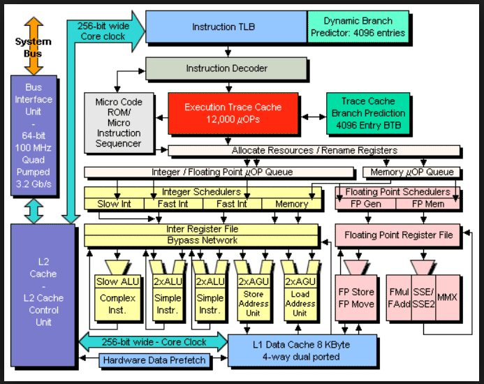 Modern Intel computers do not directly execute our assembly language
instructions. Decoders are used to make a sequence of RISC instructions,
executed in the "simple architecture" below.
Hyper Threading, just another "Hyper"
Before and after Hyper
Very small addition increased average execution from
2.5 instructions per clock to 3.5 instructions per clock
on some applications.
Modern Intel computers do not directly execute our assembly language
instructions. Decoders are used to make a sequence of RISC instructions,
executed in the "simple architecture" below.
Hyper Threading, just another "Hyper"
Before and after Hyper
Very small addition increased average execution from
2.5 instructions per clock to 3.5 instructions per clock
on some applications.
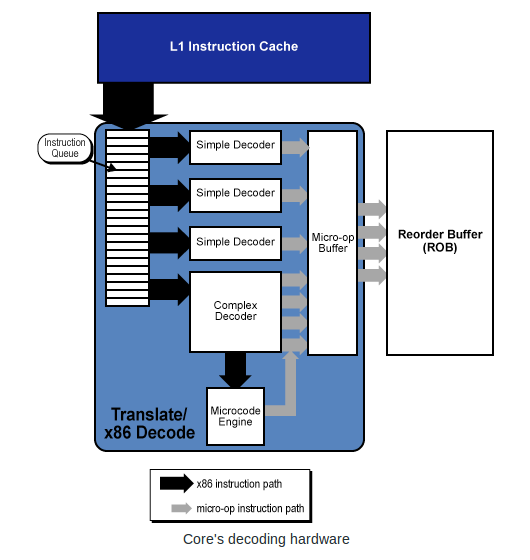 The computer architecture has a TLB, translation lookaside buffer
that translates the addresses you see in the debugger, "virtual addresses"
into a "physical address" actual RAM addresses.
That address then goes into a cache that may have the RAM data or
instruction, thus avoiding the slow RAM access.
One TLB with cache looks like the figure below.
The computer architecture has a TLB, translation lookaside buffer
that translates the addresses you see in the debugger, "virtual addresses"
into a "physical address" actual RAM addresses.
That address then goes into a cache that may have the RAM data or
instruction, thus avoiding the slow RAM access.
One TLB with cache looks like the figure below.
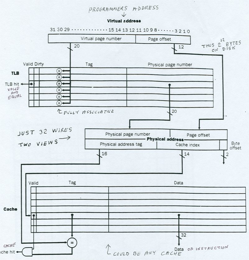 Now, a very simple architecture to follow and instruction execution.
This is after decoding instructions and TLB and cache.
PC program counter is the rip instruction pointer as a RAM address.
Instruction Memory would be section .text
Data Memory would be section .data and section .bss
ALU executes instructions mov, add, sub, imul, idiv, shift, etc.
This architecture is not Intel.
This is 32 bit MIPS computer used in SGI computers (We had one here at UMBC).
Now, a very simple architecture to follow and instruction execution.
This is after decoding instructions and TLB and cache.
PC program counter is the rip instruction pointer as a RAM address.
Instruction Memory would be section .text
Data Memory would be section .data and section .bss
ALU executes instructions mov, add, sub, imul, idiv, shift, etc.
This architecture is not Intel.
This is 32 bit MIPS computer used in SGI computers (We had one here at UMBC).
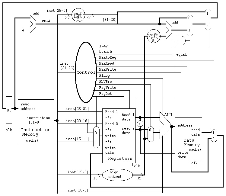 CS411 opcodes, instruction formats
mips opcodes, instruction formats
CS411 opcodes, instruction formats
mips opcodes, instruction formats
The Intel 80x86 and beyond have privilege levels.
There are instructions that can only be executed at the highest
privilege level, CPL = 0. This would be reserved for the
operating system in order to prevent the average user from
causing chaos. e.g. The average user could issue a HLT instruction
to halt the machine and thus every process would be dead.
Other CPL=0 only instructions include:
  CLTS  Clear Task Switching flag in cr0
  INVP  Invalidate cache
  INVLPG Invalidate translation lookaside buffer, TLB
  WBINVD Write Back and Invalidate cache

It should be obvious that when running a multiprocessing operating
system, that there are many instructions that only the operating
system should use.

The operating system controls the resources of the computer,
including RAM, I/O and user processes. Some sample protections
are tested by the following sample programs:

A few simple tests to be sure protections are working.
These three programs result in segfault, intentionally.
safe_64.asm store into read only section
; safe_64.asm   for testing protections within sections
; Assemble:	nasm -f elf64  safe_64.asm
; Link:		gcc -o safe_64  safe_64.o
; Run:		./safe_64
; Output:
; it should stop with a system caught error

        global main		; the standard gcc entry point
        extern	printf		; the C function, to be called

        section .rodata		; read only data section, constants
a:	dq	5		; long int a=5;
fmt:    db "Bad, still running",10,0


        section .text           ; Code section. not writeable
main:				; the program label for the entry point
        push    rbp		; set up stack frame

	mov	rax,0x789abcde
	mov	[a],rax		; should be error, read only section  !!!!!!!!!!
        mov	rdi,fmt		; address of format string
	mov	rax,0
	call	printf

        pop     rbp
	mov	rax,0		; normal, no error, return value
	ret			; return


safe1_64.asm store into code section
; safe_64.asm   for testing protections within sections
; Assemble:	nasm -f elf64   safe1_64.asm
; Link:		gcc -o safe1_64  safe1_64.o
; Run:		./safe1_64
; Output:
; it should stop with a system caught error

        global main		; the standard gcc entry point
        extern	printf		; the C function, to be called

        section .rodata		; read only data section, constants
a:	dq	5		; long int a=5;
fmt:    db "Bad, still running",10,0


        section .text           ; Code section. not writeable
main:				; the program label for the entry point
        push    rbp		; set up stack frame

	mov	rax,0x789abcde
	mov	[main],rax	; should be error, can not change code .text !!!!!!
        mov	rdi,fmt		; address of format string
	mov	rax,0
	call	printf

        pop     rbp
	mov	rax,0		; normal, no error, return value
	ret			; return


safe2_64.asm jump (execute) data
; safe2_64.asm   for testing protections within sections
; Assemble:	nasm -f elf64  safe2_64.asm
; Link:		gcc -o safe2_64  safe2_64.o
; Run:		./safe2_64
; Output:
; it should stop with a system caught error

        global main		; the standard gcc entry point
        extern	printf		; the C function, to be called

        section .rodata		; read only data section, constants
a:	dq	5		; long int a=5;
fmt:    db "Bad, still running",10,0


        section .text           ; Code section. not writeable
main:				; the program label for the entry point
        push    rbp		; set up stack frame

	mov	rax,0x789abcde
	jmp	a		; should be error, can not execute data !!!!!!!!
        mov	rdi,fmt		; address of format string
	mov	rax,0
	call	printf

        pop     rbp
	mov	rax,0		; normal, no error, return value
	ret			; return


A few simple tests to be sure privileged instructions can not execute.
priv_64.asm hlt instruction to halt computer
; priv_64.asm   for testing that average user
;               can not execute privileged instructions
; Assemble:	nasm -f elf64 priv_64.asm
; Link:		gcc -o priv_64  priv_64.o
; Run:		./priv_64
; Output:
; it should stop with a system caught error

        global main		; the standard gcc entry point
        extern	printf		; the C function, to be called
fmt:    db "bad! Still running",10,0	; The printf format, "\n",'0'


        section .text           ; try to halt the computer
main:				; the program label for the entry point
        push    rbp		; set up stack frame

	hlt			; should be error, only allowed in CPL=0  !!!!!!!

        mov	rdi,fmt		; address of format string
	mov	rax,0
	call	printf

        pop     rbp
	mov	rax,0		; normal, no error, return value
	ret			; return


priv1_64.asm other privileged instructions
; priv1_64.asm   for testing that average user
;                can not execute privileged instructions
; Assemble:	nasm -f elf64 priv1_64.asm
; Link:		gcc -o priv1_64  priv1_64.o
; Run:		./priv1_64
; Output:
; it should stop with a system caught error

        global main		; the standard gcc entry point
        extern	printf		; the C function, to be called
fmt:    db "bad! Still running",10,0	; The printf format, "\n",'0'


        section .text           ; try to halt the computer
main:				; the program label for the entry point
        push    rbp		; set up stack frame

	clts			; should be error, only allowed in CPL=0  !!!!!!!
        wbinvd			; never gets to these, also error


        mov	rdi,fmt		; address of format string
	mov	rax,0
	call	printf

        pop     rbp
	mov	rax,0		; normal, no error, return value
	ret			; return


In order to allow the user some access, controlled access, to
system resources, an interface to the operating system, or kernel,
is provided. You will see in the next lecture that some BIOS
functions are also provided as Linux kernel calls.


To implement list in NASMlist_64.c
Here is some sample code related to first "push"

; test_alist_64.asm  generating test data in heap and list
;	           (some  list_64.c  included as comments)

	extern	printf

; static char heap[20000] 	; space to store strings, do not reuse or free
; static char *hp = heap;	; pointer to next available heap space
; static long int  list[1000];	; space to store list block (2 index+ pointer)
; static long int  lp=1; 	; index to next available list space
; static char *q;    		; q, a pointer to a character
; static long int i;  		; a variable index
	section .bss
heap:	resb	20000		; could be gigabytes
list:	resq	1000		; could be millions
q:	resq	1		; may be just in  rsi
i:	resq	1		; may be just in  rdi

	section	.data
hp:	dq	heap		; [hp] is pointer to next free heap
lp:	dq	1		; index of next available list item
test:	db "middle",0, "last",0, "front",0 ; just using middle


fmt1:	db	"%s",10,0  ; "%s\n" for printf
fmtend:	db	10,0	   ; "\n"

;   push_back "middle", push_back "last", push_front "front"
;        +-----------------+   +-----------------+   +-----------------+
; L[0]-> |  index to next----->|  index to next----->|  0              |
;        |  0              |<-----index to prev  |<-----index to prev  |<-L[1]
;        | ptr to heap str |   | ptr to heap str |   | ptr to heap str |
;        +-----------------+   +-----------------+   +-----------------+
; The pointers to heap strings are character pointers to terminated strings.
; The "index" values could be pointers rather than indices.

	global main
main:
        push	rbp		; save rbp, no registers need saving
;set up test for the first push into the list

	mov	rax,1		; initial list index (*8 for address)
	mov	qword [list+8*rax],0      ; list[1]=0 no more
	mov	qword [list+8*(rax+1)],0  ; list[2]=0 no more
	mov	rbx,[hp]		    ; string address in heap
	mov	[list+8*(rax+2)],rbx ; list[3] = string address in heap
				; set L[0] = 1 = rax this is first push
				; set L[1] = 1 = rax
	mov	rbx, 0		; clear rbx, we use bl for byte
	mov	rsi, test	; similar to a push_front call
	mov	rax, [hp]	; address of heap in rax
move:	mov	bl, [rsi]	; picks up a character from test
	mov	[rax], bl	; put character on heap
	inc	rsi		; increment from address, user
	inc	rax		; increment to address, heap
	cmp	bl, 0
	jne	move
	mov	[hp],rax	; next available heap address saved

	mov	rdi, fmt1
	mov	rsi, heap
	mov	rax, 0
	call	printf

	pop	rbp
	mov	rax, 0
        ret			; return

Questions?
Help with Project ?
To understand Linux  System Calls, learn from the UMBC Expert: Gary Burt.
Note, philosophy still good, all registers starting "e" change to "r".
CMSC 313 -- System Calls

For modern 64-bit computers:
The system call numbers are the same, %eax becomes %rax, %ebx becomes %rbx, etc.
"unsigned int" becomes "unsigned long int", size_t is 64-bit, etc.
System Call Table

Another web site http://asm.sourceforge.net/syscall.html

When making Linux kernel calls from a "C" program, you will need
#include <unistd.h>

A tiny sample, using only system calls, that prints a heading
syscall0_64.asm
; syscall0_64.asm   demonstrate system, kernel, calls
; Compile:	nasm -f elf64 syscall0_64.asm
; Link		gcc -m64 -o syscall0_64 syscall0_64.o
; Run:		./syscall0_64
;
	section	.data
msg:	db  "syscall0_64.asm running",10	; the string to print, 10=crlf
len:	equ $-msg     ; "$" means here, len is a value, not an address
	global	main
	section .text
main:

; header msg			; these 5 lines are like  printf
	mov	rdx,len		; arg3, length of string to print
	mov	rcx,msg		; arg2, pointer to string
	mov	rbx,1		; arg1, where to write, screen
	mov	rax,4		; write command to int 80 hex
	int	0x80		; interrupt 80 hex, call kernel

	mov	rbx,0		; exit code, 0=normal
	mov	rax,1		; exit command to kernel
	int	0x80		; interrupt 80 hex, call kernel

Another tiny sample, using only system calls, that prints a heading
using  ld  rather than  gcc  also  _start  rather than  main

syscall0s_64.asm
; syscall0s_64.asm   demonstrate system, kernel, calls
; Compile:	nasm -f elf64 syscall0s_64.asm
; Link		ld -m64 -o syscall0s_64 syscall0s_64.o
; Run:		./syscall0s_64
;
	section	.data
msg:	db  "syscall0s_64.asm running",10	; the string to print, 10=crlf
len:	equ $-msg     ; "$" means here, len is a value, not an address
	global	_start
	section .text
_start:                         ; using ld in place of gcc

; header msg			; these 5 lines are like  printf
	mov	rdx,len		; arg3, length of string to print
	mov	rcx,msg		; arg2, pointer to string
	mov	rbx,1		; arg1, where to write, screen
	mov	rax,4		; write command to int 80 hex
	int	0x80		; interrupt 80 hex, call kernel

	mov	rbx,0		; exit code, 0=normal
	mov	rax,1		; exit command to kernel
	int	0x80		; interrupt 80 hex, call kernel


A sample syscall1_64.asm
demonstrates file open, file read (in hunks of 8192)
and file write (the whole file!)
This program reads and prints itself:

; syscall1_64.asm   demonstrate system, kernel, calls
; Compile:	nasm -f elf64 syscall1_64.asm
; Link		gcc -m64 -o syscall1_64 syscall1_64.o
; Run:		./syscall1_64
;

	section	.data
msg:	db  "syscall1_64.asm running",10	; the string to print, 10=crlf
len:	equ $-msg     ; "$" means here, len is a value, not an address
msg2:	db  "syscall1_64.asm finished",10
len2:	equ $-msg2
msg3:	db  "syscall1_64.asm opened",10
len3:	equ $-msg3
msg4:	db  "syscall1_64.asm read",10
len4:	equ $-msg4
msg5:	db  "syscall1_64.asm open fail",10
len5:	equ $-msg5
msg6:	db  "syscall1_64.asm another open fail",10
len6:	equ $-msg6
msg7:	db  "syscall1_64.asm read fail",10
len7:	equ $-msg7

name:	db  "syscall1_64.asm",0 ; "C" string also used by OS
fd:	dq  0			; file descriptor
flags:	dq  0			; hopefully read-only
	section .bss
line:	resb  8193		; read/write buffer 16 sectors of 512
lenbuf:	resq     1		; number of bytes read

	extern  open
	global	main
	section .text
main:
        push    rbp		; set up stack frame

; header msg
	mov	rdx,len		; arg3, length of string to print
	mov	rcx,msg		; arg2, pointer to string
	mov	rbx,1		; arg1, where to write, screen
	mov	rax,4		; write command to int 80 hex
	int	0x80		; interrupt 80 hex, call kernel

open1:
	mov	rdx,0		; mode
	mov	rcx,0		; flags, 'r' equivalent O_RDONLY
	mov	rbx,name	; file name to open
	mov	rax,5		; open command to int 80 hex
	int	0x80		; interrupt 80 hex, call kernel
        mov	[fd],rax	; save fd
	cmp	rax,2		; test for fail
	jg	read		; file open

; file open failed msg5
	mov	rdx,len5	; arg3, length of string to print
	mov	rcx,msg5	; arg2, pointer to string
	mov	rbx,1		; arg1, where to write, screen
	mov	rax,4		; write command to int 80 hex
	int	0x80		; interrupt 80 hex, call kernel

read:
; file opened msg3
	mov	rdx,len3	; arg3, length of string to print
	mov	rcx,msg3	; arg2, pointer to string
	mov	rbx,1		; arg1, where to write, screen
	mov	rax,4		; write command to int 80 hex
	int	0x80		; interrupt 80 hex, call kernel

doread:
	mov	rdx,8192	; max to read
	mov	rcx,line	; buffer
	mov	rbx,[fd]	; fd
	mov	rax,3		; read command to int 80 hex
	int	0x80		; interrupt 80 hex, call kernel
	mov	[lenbuf],rax	; number of characters read
	cmp	rax,0		; test for fail
	jg	readok		; some read

; read failed msg7
	mov	rdx,len7	; arg3, length of string to print
	mov	rcx,msg7	; arg2, pointer to string
	mov	rbx,1		; arg1, where to write, screen
	mov	rax,4		; write command to int 80 hex
	int	0x80		; interrupt 80 hex, call kernel
	jmp	fail		; nothing read

; file read msg4
readok:
	mov	rdx,len4	; arg3, length of string to print
	mov	rcx,msg4	; arg2, pointer to string
	mov	rbx,1		; arg1, where to write, screen
	mov	rax,4		; write command to int 80 hex
	int	0x80		; interrupt 80 hex, call kernel

write:
	mov	rdx,[lenbuf]	; length of string to print
	mov	rcx,line	; pointer to string
	mov	rbx,1		; where to write, screen
	mov	rax,4		; write command to int 80 hex
	int	0x80		; interrupt 80 hex, call kernel

fail:
; finished msg2
	mov	rdx,len2	; arg3, length of string to print
	mov	rcx,msg2	; arg2, pointer to string
	mov	rbx,1		; arg1, where to write, screen
	mov	rax,4		; write command to int 80 hex
	int	0x80		; interrupt 80 hex, call kernel

	mov	rbx,0		; exit code, 0=normal
	mov	rax,1		; exit command to kernel
	int	0x80		; interrupt 80 hex, call kernel


Now,  a little help with project 2

Arrays are pass by address and stored as address
    mov  rax, [x]  ; put address of x into rax
    mov  rbx, [y]  ; put address of y into rbx
    mov  rcx, [z]  ; put address of z into rcx

Have "C" indices in registers, must be computed and stored
    mov  r8,  [m]
    mov  r9,  [j]
    mov  r10, [k]

Now in m loop   ;    z[m] = 0.0;
    fld  qword [zero]
    fstp qword [rcx+8*r8]

in nested loops   ;      z[m] = z[m] + x[j]*y[k];
fld  qword [rax+8*r9]    x[j]
fmul qword [rbx+8*r10]   y[k]
fadd qword [rcx+8*r8]    z[m]
fstp qword [rcx+8*r8]

You are translating "C" code to assembly language

Proj2
Go over lectures 1 through 12.
Go over your project 1 solution

Sample exam will be handed out in class.

Almost all questions will be from web pages.

Closed book. Closed notes. No internet or cell phones.

Multiple choice, true-false, one number  questions.

You will not be asked to do any programming on exam.

There will be code, asking if it will assemble and
asking if it will work correctly.

First grading on project 2, this weekend
proj2 math_64.asm

z is a C array, [z] holds the address of the array in .asm file
with  C index m in r8  store a just computed value in z[m]
       mov   rcx, [z]
       mov   r8, [m]
       fstp  qword [rcx+8*r8]


convert "C" code to assembly language

   for(m=0; m<n; m++)
   {
       z[m] = 0.0;
       // stuff in loop
   }

       mov r8,0   ; m=0
form:
       fld  qword [zero]
       fstp qword [rcx+8*r8] ; zero z[m]
         ; stuff in loop

       inc r8     ; m++
       cmp r8,[n]
       jl  form   ; m<n
33 questions: some true-false, some multiple choice,
some short answer, e.g. convert decimal to binary or binary to decimal
A few one line to three line assembly language questions.
For these notes:
1 = true = high = value of a digital signal on a wire
0 = false = low = value of a digital signal on a wire
X = unknown or indeterminant to people, not on a wire
A digital logic gate can be represented at least three ways,
we will interchangeably use: schematic symbol, truth table or equation.
The equations may be from languages such as mathematics, VHDL or Verilog.
Digital logic gates are connected by wires. A wire or a group of
wires can be given a name, called a signal name. From an electronic
view the digital logic wire has a high or a low (voltage) but we
will always consider the wire to have a one (1) or a zero (0).
The basic logic gates are shown below.
The basic "and" gate:
truth table equation symbol  a b | c
----+-- c <= a and b;
0 0 | 0
0 1 | 0 c = a & b;
1 0 | 0
1 1 | 1 c = and(a,b)
Easy way to remember: The output is 1 when all inputs are 1, 0 otherwise.
In theory, an "and" gate can have any number of inputs.
a b | c
----+-- c <= a and b;
0 0 | 0
0 1 | 0 c = a & b;
1 0 | 0
1 1 | 1 c = and(a,b)
Easy way to remember: The output is 1 when all inputs are 1, 0 otherwise.
In theory, an "and" gate can have any number of inputs.
The basic "and" gate:
truth table equation symbol 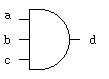 a b c | d d = and(a, b, c)
------+--
0 0 0 | 0 notice how a truth table has the inputs
0 0 1 | 0 counting 0, 1, 2, ... in binary.
0 1 0 | 0
0 1 1 | 0 the output (may be more than one bit) is
1 0 0 | 0 after the vertical line, on the right.
1 0 1 | 0
1 1 0 | 0
1 1 1 | 1
a b c | d d = and(a, b, c)
------+--
0 0 0 | 0 notice how a truth table has the inputs
0 0 1 | 0 counting 0, 1, 2, ... in binary.
0 1 0 | 0
0 1 1 | 0 the output (may be more than one bit) is
1 0 0 | 0 after the vertical line, on the right.
1 0 1 | 0
1 1 0 | 0
1 1 1 | 1
The basic "or" gate:
truth table equation symbol 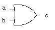 a b | c
----+-- c <= a or b;
0 0 | 0
0 1 | 1 c = a | b;
1 0 | 1
1 1 | 1 c = or(a,b)
Easy way to remember: The output is 0 when all inputs are 0, 1 otherwise.
In theory, an "or" gate can have any number of inputs.
a b | c
----+-- c <= a or b;
0 0 | 0
0 1 | 1 c = a | b;
1 0 | 1
1 1 | 1 c = or(a,b)
Easy way to remember: The output is 0 when all inputs are 0, 1 otherwise.
In theory, an "or" gate can have any number of inputs.
The basic "or" gate:
truth table equation symbol 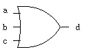 a b c | d d = or(a, b, c)
------+--
0 0 0 | 0 notice how a truth table has the inputs
0 0 1 | 1 counting 0, 1, 2, ... in binary.
0 1 0 | 1
0 1 1 | 1 the output (may be more than one bit) is
1 0 0 | 1 after the vertical line, on the right.
1 0 1 | 1
1 1 0 | 1
1 1 1 | 1
a b c | d d = or(a, b, c)
------+--
0 0 0 | 0 notice how a truth table has the inputs
0 0 1 | 1 counting 0, 1, 2, ... in binary.
0 1 0 | 1
0 1 1 | 1 the output (may be more than one bit) is
1 0 0 | 1 after the vertical line, on the right.
1 0 1 | 1
1 1 0 | 1
1 1 1 | 1
The basic "nand" gate:
truth table equation symbol 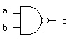 a b | c
----+-- c <= a nand b;
0 0 | 1
0 1 | 1 c = ~ (a & b);
1 0 | 1
1 1 | 0 c = nand(a,b)
Easy way to remember: "nand" reads "not and", the complement of "and".
a b | c
----+-- c <= a nand b;
0 0 | 1
0 1 | 1 c = ~ (a & b);
1 0 | 1
1 1 | 0 c = nand(a,b)
Easy way to remember: "nand" reads "not and", the complement of "and".
The basic "nor" gate:
truth table equation symbol 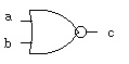 a b | c
----+-- c <= a nor b;
0 0 | 1
0 1 | 0 c = ~ (a | b);
1 0 | 0
1 1 | 0 c = nor(a,b)
Easy way to remember: "nor" reads "not or", the complement of "or".
a b | c
----+-- c <= a nor b;
0 0 | 1
0 1 | 0 c = ~ (a | b);
1 0 | 0
1 1 | 0 c = nor(a,b)
Easy way to remember: "nor" reads "not or", the complement of "or".
The basic "xor" gate:
truth table equation symbol  a b | c
----+-- c <= a xor b;
0 0 | 0
0 1 | 1 c = a ^ b;
1 0 | 1
1 1 | 0 c = xor(a,b)
Easy way to remember: "eXclusive or" not 11, or odd number of ones.
a b | c
----+-- c <= a xor b;
0 0 | 0
0 1 | 1 c = a ^ b;
1 0 | 1
1 1 | 0 c = xor(a,b)
Easy way to remember: "eXclusive or" not 11, or odd number of ones.
The basic "xor" gate:
truth table equation symbol 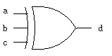 a b c | d
------+-- d <= a xor b xor c;
0 0 0 | 0
0 0 1 | 1
0 1 0 | 1 d = a ^ b ^ c;
0 1 1 | 0
1 0 0 | 1 d = xor(a,b,c)
1 0 1 | 0
1 1 0 | 0
1 1 1 | 1
Easy way to remember: odd parity, odd number of ones.
a b c | d
------+-- d <= a xor b xor c;
0 0 0 | 0
0 0 1 | 1
0 1 0 | 1 d = a ^ b ^ c;
0 1 1 | 0
1 0 0 | 1 d = xor(a,b,c)
1 0 1 | 0
1 1 0 | 0
1 1 1 | 1
Easy way to remember: odd parity, odd number of ones.
The basic "xnor" gate:
truth table equation symbol  a b | c
----+-- c <= a xnor b;
0 0 | 1
0 1 | 0 c = ~ (a ^ b);
1 0 | 0
1 1 | 1 c = xnor(a,b)
Easy way to remember: "xnor" reads "not xor", equality or even parity.
a b | c
----+-- c <= a xnor b;
0 0 | 1
0 1 | 0 c = ~ (a ^ b);
1 0 | 0
1 1 | 1 c = xnor(a,b)
Easy way to remember: "xnor" reads "not xor", equality or even parity.
The basic "not" gate:
truth table equation symbol 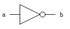 a | b
--+-- b <= not a;
0 | 1
1 | 0 b = ~ a;
b = not(a)
Easy way to remember: invert or "not", the complement.
a | b
--+-- b <= not a;
0 | 1
1 | 0 b = ~ a;
b = not(a)
Easy way to remember: invert or "not", the complement.
A specialized gate:
truth table equation symbol 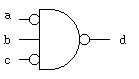 a b c | d
------+-- d <= not( not a and b and not c);
0 0 0 | 1
0 0 1 | 1
0 1 0 | 0 d = ~( ~a & b & ~c);
0 1 1 | 1
1 0 0 | 1 d = not(and(not(a),b,not(c)))
1 0 1 | 1 _______
1 1 0 | 1 _ _
1 1 1 | 1 d = (a b c)
Easy way to remember: none, just work it out.
Bubbles on the input mean the same as bubbles on the output,
invert the signal value. Often this is written with a line
_ _
above the variable d = a b c which is read:
d equals a bar and b and c bar. The word "bar" for the line
above the variable, meaning invert the variable.
It is known that there are 16 Boolean functions with two inputs.
In fact, for any number of inputs, n, there are 2^(2^n) Boolean
functions ( two to the power of two to the nth).
For n=2 16 functions 2^4
n=3 256 functions 2^8
n=4 65,536 functions 2^16
n=5 over four billion functions 2^32
The truth table for all Boolean functions of two inputs is
n x
n x a a n
o _ _ o n n o 1 1 o
a b | 0 r 2 a 4 b r d d r b 1 a 3 r 1
----+--------------------------------
0 0 | 0 1 0 1 0 1 0 1 0 1 0 1 0 1 0 1
0 1 | 0 0 1 1 0 0 1 1 0 0 1 1 0 0 1 1
1 0 | 0 0 0 0 1 1 1 1 0 0 0 0 1 1 1 1
1 1 | 0 0 0 0 0 0 0 0 1 1 1 1 1 1 1 1
Notice that for two input variables, a b, there are 2^2 = 4 rows
Notice that for four rows there are 2^4 = 16 columns.
A question is: Which are "universal" functions from which all
other functions can be obtained?
The answer is that either "nand" or "nor" can be used to create
all other functions (when having 0 and 1 available). It turns out
that electric circuits rather naturally create "nand" or "nor"
gates. No more than five "nand" gates or five "nor" gates are
needed in creating any of the 16 Boolean functions of two inputs.
Here are the circuits using only "nand" to get all 16 functions.
Example and-or logic converted to only nand logic:
fadd_v.out
Generated by program, digital logic simulator, verilog
fadd.v
There are many notations used for digital logic:
a, b, c are boolean variables:
c = a + b means c = a or b
c = ab means c = a and b
c = a * b means c = a and b
_
c = a means c = not a
c = -a means c = not a
Then, there is more than just 0 and 1 values a boolean variable may have:
H = 1 high, weak
L = 0 low, weak
X = unknown
Z = high impedance, usually open circuit, or bus
W = unknown, weak
U = uninitialized
- = don't care = X = unknown
Truth tables for and, or, ... using all VHDL std_logic signal values:
t_table.out
Generated by program, digital logic simulator, VHDL
t_table.vhdl
Similarly, for verilog
t_table_v.out
Generated by program, digital logic simulator, verilog
t_table.v
Some of these values only become useful when two gate outputs
are connected together, this may be a "wired and" or
a "wired or" depending on how the circuit is implemented
in silicone. If two wires are connected together and one
is high impedance, Z, then the other wire would control.
Also, weak will be controlled by the other wire.
You also have available logisim graphical logic simulator, see:
logisim.run
small circuit in logicsim
a b c | d
------+-- d <= not( not a and b and not c);
0 0 0 | 1
0 0 1 | 1
0 1 0 | 0 d = ~( ~a & b & ~c);
0 1 1 | 1
1 0 0 | 1 d = not(and(not(a),b,not(c)))
1 0 1 | 1 _______
1 1 0 | 1 _ _
1 1 1 | 1 d = (a b c)
Easy way to remember: none, just work it out.
Bubbles on the input mean the same as bubbles on the output,
invert the signal value. Often this is written with a line
_ _
above the variable d = a b c which is read:
d equals a bar and b and c bar. The word "bar" for the line
above the variable, meaning invert the variable.
It is known that there are 16 Boolean functions with two inputs.
In fact, for any number of inputs, n, there are 2^(2^n) Boolean
functions ( two to the power of two to the nth).
For n=2 16 functions 2^4
n=3 256 functions 2^8
n=4 65,536 functions 2^16
n=5 over four billion functions 2^32
The truth table for all Boolean functions of two inputs is
n x
n x a a n
o _ _ o n n o 1 1 o
a b | 0 r 2 a 4 b r d d r b 1 a 3 r 1
----+--------------------------------
0 0 | 0 1 0 1 0 1 0 1 0 1 0 1 0 1 0 1
0 1 | 0 0 1 1 0 0 1 1 0 0 1 1 0 0 1 1
1 0 | 0 0 0 0 1 1 1 1 0 0 0 0 1 1 1 1
1 1 | 0 0 0 0 0 0 0 0 1 1 1 1 1 1 1 1
Notice that for two input variables, a b, there are 2^2 = 4 rows
Notice that for four rows there are 2^4 = 16 columns.
A question is: Which are "universal" functions from which all
other functions can be obtained?
The answer is that either "nand" or "nor" can be used to create
all other functions (when having 0 and 1 available). It turns out
that electric circuits rather naturally create "nand" or "nor"
gates. No more than five "nand" gates or five "nor" gates are
needed in creating any of the 16 Boolean functions of two inputs.
Here are the circuits using only "nand" to get all 16 functions.
Example and-or logic converted to only nand logic:
fadd_v.out
Generated by program, digital logic simulator, verilog
fadd.v
There are many notations used for digital logic:
a, b, c are boolean variables:
c = a + b means c = a or b
c = ab means c = a and b
c = a * b means c = a and b
_
c = a means c = not a
c = -a means c = not a
Then, there is more than just 0 and 1 values a boolean variable may have:
H = 1 high, weak
L = 0 low, weak
X = unknown
Z = high impedance, usually open circuit, or bus
W = unknown, weak
U = uninitialized
- = don't care = X = unknown
Truth tables for and, or, ... using all VHDL std_logic signal values:
t_table.out
Generated by program, digital logic simulator, VHDL
t_table.vhdl
Similarly, for verilog
t_table_v.out
Generated by program, digital logic simulator, verilog
t_table.v
Some of these values only become useful when two gate outputs
are connected together, this may be a "wired and" or
a "wired or" depending on how the circuit is implemented
in silicone. If two wires are connected together and one
is high impedance, Z, then the other wire would control.
Also, weak will be controlled by the other wire.
You also have available logisim graphical logic simulator, see:
logisim.run
small circuit in logicsim
Combinational digital logic uses Boolean Algebra.
The basic relations are well known, yet several notations
are used.
When using binary arithmetic on binary numbers and using
the least significant bit of the result:
Notation A: use words "and" "or" "not" etc.
Notation B: use characters & for "and", | for "or", ~ for "not"
Notation C: use characters * for "and", + for "or", - for "not"
Notation D: use symbols "dot" for "and", + for "or", bar for "not"
Notation E: use symbols "blank" for "and", + for "or", bar for "not"
Generally, the symbols for "and" are like the symbols for multiply,
the symbols for "or" are like the symbols for addition.
In mathematics, multiplication always has precedence over addition,
do not expect "and" to always have precedence over "or.
Here are 19 basic identities that can be used to simplify
or convert one Boolean equation to another.
1. X + 0 = X "or" anything with zero gives anything
2. X * 1 = X "and" anything with one gives anything
3. X + 1 = 1 "or" anything with one gives one
4. X * 0 = 0 "and" anything with zero gives zero
5. X + X = X "or" with self gives self
6. X * X = X "and" with self gives self
_
7. X + X = 1 "or" with complement gives one
_
8. X * X = 0 "and" with complement gives zero
9. not(not(X)) = X any even number of complements cancel
10. X + Y = Y + X "or" is commutative
11. X * Y = Y * X "and" is commutative
12. X + (Y + Z) = (X + Y) + Z "or" is associative
13. X * (Y * Z) = (X * Y) * Z "and" is associative
14. X * (Y + Z) = X * Y + X * Z distributive law
15. X + Y * Z = (X + Y) * (X + Z) distributive law
_________
_ _
16. X + Y = ( X * Y ) DeMorgan's theorem
_________ _ _
17. ( X + Y ) = X * Y DeMorgan's theorem
_________ _ _
18. ( X * Y ) = X + Y DeMorgan's theorem
_________
_ _
19. X * Y = ( X + Y ) DeMorgan's theorem
Basically, DeMorgan's theorem says:
Convert "and" to "or", negate the variables and negate the entire expression.
Convert "or" to "and", negate the variables and negate the entire expression.
Any truth table can be converted to a equation or schematic.
Given any truth table, there is a simple procedure for generating
a Boolean equation that uses "and", "or" and "not" (any representation).
First an example:
Given truth table
a b | c for each row where 'c' is 1, _
----+-- create an "and" with 'a' if 'a' is 1, or 'a' if 'a' is 0
0 0 | 1 _
0 1 | 0 with 'b' if 'b' is 1, or 'b' if 'b' is 0
1 0 | 1 _ _
1 1 | 1 thus, first row a * b
_
third row a * b
fourth row a * b
now, "or" the "and's" to form the final equation
_ _ _
c = (a * b) + (a * b) + (a * b)
c <= (not a and not b) or (a and not b) or (a and b);
The schematic can be drawn directly,
one "and" gate for each row where 'c' is 1
with a bubble for each variable that is 0
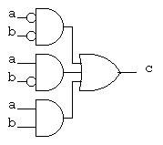 The general process to convert a truth table (or partial truth table)
to a Boolean equation using "and" "or" "not" is:
For each output
For each row where the output is 1
create a minterm that is the "and" of the input variables with
the input variable complemented when the input variable is 0.
The output is the "or" of the above minterms.
Another example with three input variables and two outputs.
a b c | s co
------+-----
0 0 0 | 0 0 _ _ _ _ _ _
0 0 1 | 1 0 s = (a*b*c) + (a*b*c) + (a*b*c) + (a*b*c)
0 1 0 | 1 0
0 1 1 | 0 1 _ _ _
1 0 0 | 1 0 co = (a*b*c) + (a*b*c) + (a*b*c) + (a*b*c)
1 0 1 | 0 1
1 1 0 | 0 1
1 1 1 | 1 1
(Note 4 outputs '1' in truth table, 4 and expressions ored)
The exact same information is presented by the schematic:
(Note 4 outputs '1' in truth table, 4 and gates feed 1 or gate)
The general process to convert a truth table (or partial truth table)
to a Boolean equation using "and" "or" "not" is:
For each output
For each row where the output is 1
create a minterm that is the "and" of the input variables with
the input variable complemented when the input variable is 0.
The output is the "or" of the above minterms.
Another example with three input variables and two outputs.
a b c | s co
------+-----
0 0 0 | 0 0 _ _ _ _ _ _
0 0 1 | 1 0 s = (a*b*c) + (a*b*c) + (a*b*c) + (a*b*c)
0 1 0 | 1 0
0 1 1 | 0 1 _ _ _
1 0 0 | 1 0 co = (a*b*c) + (a*b*c) + (a*b*c) + (a*b*c)
1 0 1 | 0 1
1 1 0 | 0 1
1 1 1 | 1 1
(Note 4 outputs '1' in truth table, 4 and expressions ored)
The exact same information is presented by the schematic:
(Note 4 outputs '1' in truth table, 4 and gates feed 1 or gate)
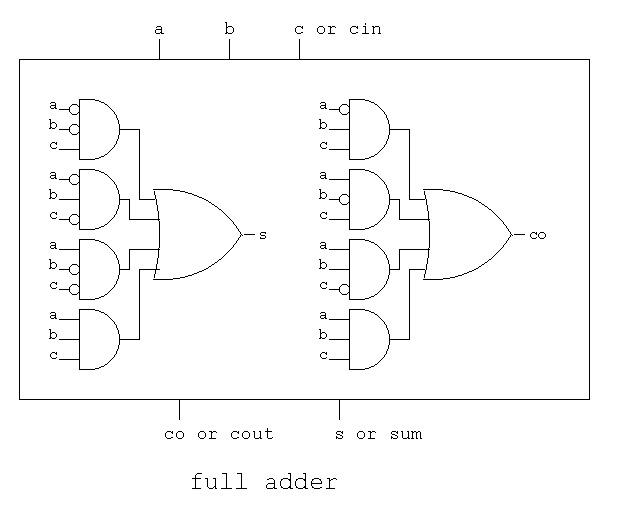 Note that this is not a minimum representation, we will talk
about minimizing digital logic in a few lectures.
Note that this is not a minimum representation, we will talk
about minimizing digital logic in a few lectures.
Any equation can be converted to a truth table.
Example, convert c <= (a and b) or (not a and b);
_
c = (a * b) + (a * b) to a truth table
We can immediately construct the truth table structure.
We see the input variables are 'a' and 'b' and the output is 'c'
We generate all possible values for input by counting in binary.
a b | c
----+--
0 0 |
0 1 |
1 0 |
1 1 |
The only step that remains is to fill in the 'c' column.
For the first row, substitute 0 for 'a' and 0 for 'b' in the
equation and evaluate to find 'c'
_
c = (0 * 0) + (0 * 0) = (0) + ( 1 * 0) = 0 (using identities above)
For the second row, substitute 0 for 'a' and 1 for 'b' in the
equation and evaluate to find 'c'
_
c = (0 * 1) + (0 * 1) = (0) + ( 1 * 1) = 1 (using identities above)
For the third row, substitute 1 for 'a' and 0 for 'b' in the
equation and evaluate to find 'c'
_
c = (1 * 0) + (1 * 0) = (0) + ( 0 * 0) = 0 (using identities above)
For the fourth row, substitute 1 for 'a' and 1 for 'b' in the
equation and evaluate to find 'c'
_
c = (1 * 1) + (1 * 1) = (1) + ( 0 * 1) = 1 (using identities above)
Filling in the values for 'c' gives the completed truth table:
a b | c
----+--
0 0 | 0
0 1 | 1
1 0 | 0
1 1 | 1
Any digital logic schematic can be converted to a truth table.
Any equation can be converted to a schematic and any schematic
can be converted to an equation. When converting a schematic to
a truth table directly, you are simulating the actual behavior
of the digital logic.
From schematic below we can immediately construct the truth table structure.
We see the input variables are 'a' and 'b' and the output is 'c'
We generate all possible values for input by counting in binary.
a b | c
----+--
0 0 |
0 1 |
1 0 |
1 1 |
Now, start by placing the values of input signals on the
input wires. a=0, b=0.
Note that signals other than inputs are labeled X for unknown.
Then, as shown on the sequence of figures, propagate the signals.
For each gate, use the gate input to compute the gate output.
This is actually how the hardware works. Each gate is continually
using the inputs to produce the output, with a small delay.
All gates operate in parallel. All gates operate all the time.
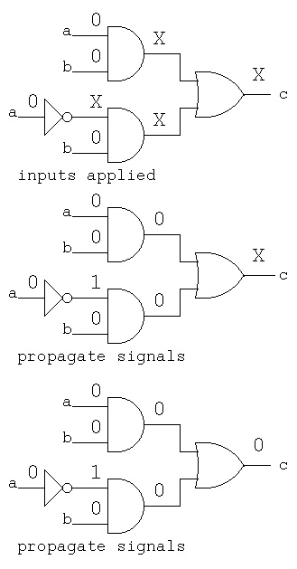 Working a little faster, apply truth table inputs
a=0, b=1, then a=1, b=0, and finally a=1, b=1.
Working a little faster, apply truth table inputs
a=0, b=1, then a=1, b=0, and finally a=1, b=1.
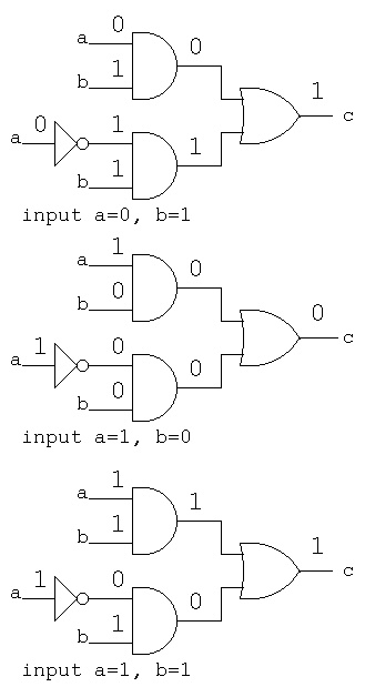 Filling in the values for 'c' gives the completed truth table:
a b | c
----+--
0 0 | 0
0 1 | 1
1 0 | 0
1 1 | 1
The previous lecture shows generating truth tables
with VHDL or Verilog logic simulators.
Diagrams made with logisim can have inputs set to 0 or 1
then simulate and see values of outputs:
Filling in the values for 'c' gives the completed truth table:
a b | c
----+--
0 0 | 0
0 1 | 1
1 0 | 0
1 1 | 1
The previous lecture shows generating truth tables
with VHDL or Verilog logic simulators.
Diagrams made with logisim can have inputs set to 0 or 1
then simulate and see values of outputs:
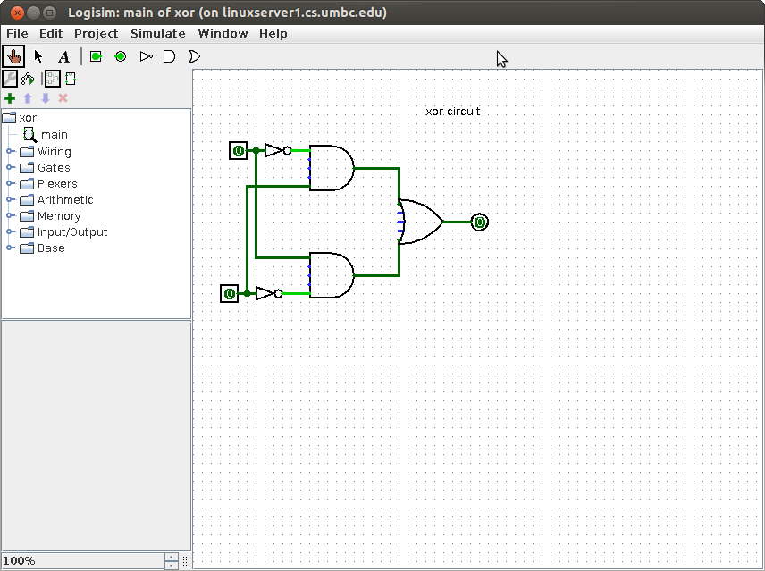
"Combinational logic" means gates connected together without feedback.
There is no storage of information. Inputs are applied and outputs
are produced. By convention, we draw combinational logic from
inputs on the left to outputs on the right. For large schematic
diagrams this convention is often violated.
When no constraints are given, any of the gates previously
defined can be connected to design a circuit that performs
the stated function.
Example: Design a circuit that has:
an input for tail lights both on (break pedal in car)
an input for right turn that lets the signal "osc" control right tail light.
an input for left turn that lets the signal "osc" control left tail light.
("osc" will make the light flash on and off as a turn indicator.)
Constraint: use "and" and "or" gates with inversion bubbles allowed
Solution: There are four inputs "tail" "right" "left" and "osc"
There are two outputs "right_light" and "left_light"
The general strategy in design is to work backward from an output.
Yet, as usual, some work from input toward output is also used.
"right_light" must select between "tail" and "osc". Selection
can typically be implemented by "and" gates feeding an "or" gate
with a control signal into one "and" gate and its complement into
the other "and" gate.
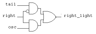 Analyzing this circuit, if "right" is off, "tail" controls
the "right_light". If "right is on, "osc" controls the "right_light".
in VHDL right_light <= (tail and not right) or (right and osc);
tail.vhdl
tail_vhdl.out
in Verilog right_light = (tail & ~right) | (right & osc);
tail.v
tail_v.out
A common symbol for this circuit is a multiplexor, mux for short.
The same circuit as above is usually drawn as the schematic diagram:
Analyzing this circuit, if "right" is off, "tail" controls
the "right_light". If "right is on, "osc" controls the "right_light".
in VHDL right_light <= (tail and not right) or (right and osc);
tail.vhdl
tail_vhdl.out
in Verilog right_light = (tail & ~right) | (right & osc);
tail.v
tail_v.out
A common symbol for this circuit is a multiplexor, mux for short.
The same circuit as above is usually drawn as the schematic diagram:
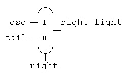 Now we can use the first schematic with new labeling for
the "left_light", combining the circuits yields:
Now we can use the first schematic with new labeling for
the "left_light", combining the circuits yields:
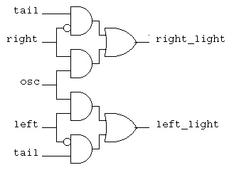 Now a new requirement is added, the flashers must over ride all
other signals and make "osc" drive both right and left tail lights.
A typical design technique is to build on existing designs,
thus note that "flash" only needs to be able to turn on both
the old "right" and old "left". This is two "or" functions
that are easily added to the previous circuit.
Now a new requirement is added, the flashers must over ride all
other signals and make "osc" drive both right and left tail lights.
A typical design technique is to build on existing designs,
thus note that "flash" only needs to be able to turn on both
the old "right" and old "left". This is two "or" functions
that are easily added to the previous circuit.
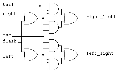 In general a multiplexor can have any number of inputs.
Typically the number of inputs is a power of two and the
control signal, ctl, has the number of bits in the power.
In general a multiplexor can have any number of inputs.
Typically the number of inputs is a power of two and the
control signal, ctl, has the number of bits in the power.
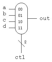 ctl | out Note that "ctl" is a two bit signal, shown by the "2"
----+----
0 0 | a The truth table does not have to expand
0 1 | b a, b, c and d because the mux just passes
1 0 | c the values through to "out" based on the
1 1 | d value of "ctl"
This mux coded in VHDL would be:
entity mux_4 is
port(
a : in std_logic;
b : in std_logic;
c : in std_logic;
d : in std_logic;
ctl : in std_logic vector (1 downto 0));
result : out std_logic;
end entity mux_4;
architecture behavior of mux_4 is
begin -- behavior -- no process needed with concurrent statements
result <= b when ctl='01' else c when ctl='10' else d when ctl='11'
else a after 250 ps;
end architecture behavior; -- of mux_4
This mux coded in verilog would be:
module mux_4to1_assign (
input a,
input b,
input c,
input d,
input ctl,
output out);
assign out = ctl[1] ? (ctl[0] ? d : c) : (ctl[0] ? b : a);
endmodule
For a general circuit that has some type of description, we use
a rectangle with some notation indicating the function of the
circuit. The inputs and outputs are given signal names.
ctl | out Note that "ctl" is a two bit signal, shown by the "2"
----+----
0 0 | a The truth table does not have to expand
0 1 | b a, b, c and d because the mux just passes
1 0 | c the values through to "out" based on the
1 1 | d value of "ctl"
This mux coded in VHDL would be:
entity mux_4 is
port(
a : in std_logic;
b : in std_logic;
c : in std_logic;
d : in std_logic;
ctl : in std_logic vector (1 downto 0));
result : out std_logic;
end entity mux_4;
architecture behavior of mux_4 is
begin -- behavior -- no process needed with concurrent statements
result <= b when ctl='01' else c when ctl='10' else d when ctl='11'
else a after 250 ps;
end architecture behavior; -- of mux_4
This mux coded in verilog would be:
module mux_4to1_assign (
input a,
input b,
input c,
input d,
input ctl,
output out);
assign out = ctl[1] ? (ctl[0] ? d : c) : (ctl[0] ? b : a);
endmodule
For a general circuit that has some type of description, we use
a rectangle with some notation indicating the function of the
circuit. The inputs and outputs are given signal names.
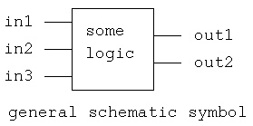
There are many simulation and design tools available for digital logic.

Some sections of CMSC 313 use Logisim a Java applet that can be run
from any WEB browser. Logisim is interactive and dynamic yet seems
limited in circuit complexity and timing accuracy. Learn more at
Logisim WEB page

There are major commercial Electronic Design Automation, EDA, systems
for todays digital logic. Cadence is one of todays major suppliers and
UMBC has Cadence software available on GL computers.
Mentor Graphics, Synopsis and others provide large tool sets.

Altera and Xilinx are major providers of software for making custom
integrated circuits using Field Programmable Gate Arrays, FPGA.
 www.altera.com
Altera has a downloadable student version.
 www.xilinx.com


A WEB site to find simulators on wikipedia

For projects for this section of CMSC 313 we will use Cadence VHDL
and Cadence Verilog that are available on linux.gl.umbc.edu.
Using Cadence VHDL on Linux.GL machines
  First: You must have an account on a GL machine. Every student
         and faculty should have this.
         Either log in directly to linux.gl.umbc.edu or
         Use:
         ssh  linux.gl.umbc.edu
         csh       # VHDL needs the C shell, not the Bash shell
         cd cs313  # or replace this with the directory you are using

  Next:  Follow instructions exactly for VHDL.
         To get cs313.tar file into your cs313 directory (on /afs  i.e.
         available on all GL machines.)

         cp /afs/umbc.edu/users/s/q/squire/pub/download/cs313.tar  .
         tar -xvf cs313.tar  # this makes subdirectory vhdl with files
         cd vhdl
         "edit cds.lib  put your directory after $HOME/
                            for example    $HOME/cs313/vhdl
                  DEFINE vhdl_lib $HOME/vhdl/vhdl_lib
         source vhdl_cshrc
         make
         more add32_test.out
         make clean              # saves a lot of disk quota

         Then do your own thing with Makefile for other VHDL files

         Remember each time you log on to do simulations:
         csh
         cd cs313/vhdl/
         source vhdl_cshrc
         make                        # or do your own thing.

For Verilog, create a Makefile, make changes
cut and paste following command once

source /afs/umbc.edu/software/cadence/etc/setup_2008/cshrc.cadence

Makefile for Cadence Verilog-XL
all: hello.out

hello.out: hello.v
	verilog -q -l hello.out hello.v
FPGA and other CAD information
You can get working chips from VHDL using synthesis tools.

One of the quickest ways to get chips is to use FPGA's,
Field Programmable Gate Arrays.
The two companies listed below provide the software and the
foundry for you to design your own integrated circuit chips:

 www.altera.com

 www.xilinx.com

Complete Computer Aided Design, CAD, packages are available from
companies such as Cadence, Mentor Graphics and Synopsis.


"Hello World sample programs
As usual, learn a language by starting with a simple "hello" program:

VHDL  hello.vhdl
hello.run used in simulation
hello_vhdl.out output of simulation

Note two major parts of a VHDL program:
The "entity" is the interface, and the "architecture" is the implementation.
     hello                              circuits

-- hello.vhdl  Just output to the screen
-- compile and run commands
-- 	ncvhdl -v93 hello.vhdl
--	ncelab -v93 hello:circuits
--	ncsim -batch  -logfile hello_vhdl.out -input hello.run hello


entity hello is  -- test bench (top level like "main")
end entity hello;

library STD;
use STD.textio.all;                     -- basic I/O
library IEEE;
use IEEE.std_logic_1164.all;            -- basic logic types
use IEEE.std_logic_textio.all;          -- I/O for logic types

architecture circuits of hello is -- where declarations are placed
  subtype word_32 is std_logic_vector(31 downto 0);
  signal four_32 : word_32 := x"00000004";    -- just four
  signal counter : integer := 1;              -- initialized counter
  alias swrite is write [line, string, side, width] ;
begin  -- where code is placed
  my_print : process is
               variable my_line : line;  -- type 'line' comes from textio
             begin
               write(my_line, string'("Hello VHDL"));  -- formatting
               writeline(output, my_line);              -- write to "output"
               swrite(my_line, "four_32 = ");     -- formatting with alias
               hwrite(my_line, four_32); -- format type std_logic_vector as hex
               swrite(my_line, "  counter= ");
               write(my_line, counter);  -- format 'counter' as integer
               swrite(my_line, " at time ");
               write(my_line, now);                     -- format time
               writeline(output, my_line);              -- write to display
               wait;
             end process my_print;
end architecture circuits;


 Verilog hello.v
hello_v.out output of simulation

// hello.v   First Verilog program
// command to compile and run
//         verilog -q -l hello_v.out hello.v

module hello;
  reg [31:0] four_32;
  integer counter;

  initial
    begin
      four_32 = 32'b00000000000000000000000000000100;
      counter = 1;
      $display("Hello Verilog");
      $display("%b", four_32);
      $display("counter = %d", counter);
    end
endmodule // hello

// output
// Hello Verilog
// 00000000000000000000000000000100
// counter =           1


Truth Tables For possible use with homework 4

VHDL  t_table4.vhdl
t_table4.run used in simulation
t_table4.out output of simulation

-- t_table4.vhdl

library STD;
use STD.textio.all;
library IEEE;
use IEEE.std_logic_1164.all;
use IEEE.std_logic_textio.all;
use IEEE.std_logic_arith.all;

entity t_table4 is
end t_table4;

architecture circuits of t_table4 is

  procedure v_print( title : string ) is
    variable my_line : line;
  begin
    writeline(output, my_line); -- blank line
    write(my_line, "a b c  | d    " & title);
    writeline(output, my_line);
    write(my_line, string'("-------+----"));
    writeline(output, my_line);
  end v_print;

  procedure t_print(a : std_logic;
                    b : std_logic;
                    c : std_logic;
                    d : std_logic) is
    variable my_line : line;
  begin
    write(my_line, a);
    write(my_line, string'(" "));
    write(my_line, b);
    write(my_line, string'(" "));
    write(my_line, c);
    write(my_line, string'("  | "));
    write(my_line, d);
    writeline(output, my_line);
  end t_print;

begin  -- test of t_table4
  driver: process                      -- serial code
            variable a, b, c, d : std_logic;
            variable my_line : LINE;
            variable bits:  std_logic_vector(1 downto 0) := ('1','0');

  begin  -- process driver
            write(my_line, string'("Truth table."));
            writeline(output, my_line);
            v_print("d := not a and b and not c ;");
            for i in 0 to 1 loop
              a := bits(i);
              for j in 0 to 1 loop
                b := bits(j);
                for k  in 0 to 1 loop
                  c := bits(k);

                  d := not a and b and not c;
                  t_print(a, b, c, d);
                end loop;  -- c
              end loop; -- b
            end loop; -- a
            wait for 2 ns;
          end process driver;
end architecture circuits;   -- of t_table4

ncsim: 06.11-s008: (c) Copyright 1995-2007 Cadence Design Systems, Inc.
ncsim> run 2 ns
Truth table.

a b c  | d    d := not a and b and not c ;
-------+----
0 0 0  | 0
0 0 1  | 0
0 1 0  | 1
0 1 1  | 0
1 0 0  | 0
1 0 1  | 0
1 1 0  | 0
1 1 1  | 0
Ran until 2 NS + 0
ncsim> exit


 Verilog t_table4.v
t_table4_v.out output of simulation

// t_table4.v

`timescale 1ns/1ns // set time unit and time lsb
module t_table4;
  reg a, b, c, d;
  integer i, j, k;
  reg val[1:2];
  initial
    begin
      val[1] = 0;
      val[2] = 1;
      $display("a b c | d = ~a*b*~c");
      $display("------+---");

      for(i=1; i<=2; i=i+1)
      begin
        a = val[i];
        for(j=1; j<=2; j=j+1)
        begin
          b = val[j];
	  for(k=1; k<=2; k=k+1)
	  begin
            c = val[k];

	    d = ~a*b*~c;  // equation for truth table
            $display("%b %b %b | %b", a, b, c, d);
	  end
        end
      end
    end
endmodule

// output
a b c | d = ~a*b*~c
------+---
0 0 0 | 0
0 0 1 | 0
0 1 0 | 1
0 1 1 | 0
1 0 0 | 0
1 0 1 | 0
1 1 0 | 0
1 1 1 | 0
Other Digital Logic Tool Links
Personal effort plus automation:
Your plane will be ready soon
Basic decimal addition (with carry digit shown)
101 <- carry (note that three numbers are added after first digit)
567
+ 526
-----
1093
Binary addition (with carry bit shown)
1011 <- carry (note that three bits are added after first bit)
for future reference c(3)=1, c(2)=0, c(1)=1, c(0)=1
1011 bits are numbered from zero, right to left
+ 1001
-----
10100 for future reference s(3)=0, s(2)=1, s(1)=0, s(0)=0
the leftmost '1' is cout
Since three bits must be added, a truth table for a full adder
needs three inputs and thus eight entries.
a b c | s co
------+----- _ _ _ _ _ _
0 0 0 | 0 0 s = (a*b*c) + (a*b*c) + (a*b*c) + (a*b*c)
0 0 1 | 1 0 simplifies to
0 1 0 | 1 0 s = a xor b xor c
0 1 1 | 0 1 s <= a xor b xor c;
1 0 0 | 1 0 _ _ _
1 0 1 | 0 1 co = (a*b*c) + (a*b*c) + (a*b*c) + (a*b*c)
1 1 0 | 0 1 simplifies to
1 1 1 | 1 1 co = (a*b)+(a*c)+(b*c)
co <= (a and b) or (a and c) or (b and c);
This can be drawn as a box for use on larger schematics
+-------+
| a b c | The inputs are shown at the top (or right)
| |
| fadd |
| |
| co s | The outputs are shown at the bottom (or left)
+-------+
This is easier than copying as a schematic
The full adder can be written as an entity in VHDL
entity fadd is -- full stage adder, interface
port(a : in std_logic;
b : in std_logic;
c : in std_logic;
s : out std_logic;
co : out std_logic);
end entity fadd;
architecture circuits of fadd is -- full adder stage, body
begin -- circuits of fadd
s <= a xor b xor c after 1 ns;
co <= (a and b) or (a and c) or (b and c) after 1 ns;
end architecture circuits; -- of fadd
The full adder can be written as a module in Verilog
module fadd(a, b, cin, sum, cout); // from truth table
input a; // a input
input b; // b input
input cin; // carry-in
output sum; // sum output
output cout; // carry-out
assign sum = (~a*~b*cin)+(~a*b*~cin)+(a*~b*~cin)+(a*b*cin);
assign cout = (a*b)+(a*cin)+(b*cin); // last term redundant
endmodule // fadd
Connecting four full adders, four fadd's, to make a 4-bit adder
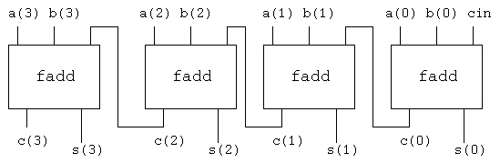 c(3) should be cout
The connections are written for VHDL as
a0: entity WORK.fadd port map(a(0), b(0), cin, s(0), c(0));
a1: entity WORK.fadd port map(a(1), b(1), c(0), s(1), c(1));
a2: entity WORK.fadd port map(a(2), b(2), c(1), s(2), c(2));
a3: entity WORK.fadd port map(a(3), b(3), c(2), s(3), cout);
The connections are written for Verilog as
// instantiate modules
fadd bit0(a[0], b[0], cin, sum[0], c[0]);
fadd bit1(a[1], b[1], c[0], sum[1], c[1]);
fadd bit2(a[2], b[2], c[1], sum[2], c[2]);
fadd bit3(a[3], b[3], c[2], sum[3], cout);
Note that the carry out of the previous stage is wired into
the carry input of the next higher stage. In a computer,
four bits are added to four bits and this produces four bits of sum.
The last carry bit, c(3) here, is usually called 'cout' and is
not called a 'sum' bit.
The VHDL circuit was simulated with
a(3)=0, a(2)=0, a(1)=0, a(0)=1 cin=0
b(3)=1, b(2)=1, b(1)=1, b(0)=1
There is a small delay time from the input to the output.
When a circuit is simulated, the initial values of signals
are shown as 'U' for uninitialized. As the circuit simulation
proceeds, the 'U' are computed and become '0' or '1'.
Partial output from the VHDL simulation shows this propagation.
(the upper line is logic '1', the lower line is logic '0')
s(0) UU_____________________________
s(1) UUUUUU_________________________
s(2) UUUUUUUUUU_____________________
s(3) UUUUUUUUUUUUUU_________________
____________________________
c(0) UU
________________________
c(1) UUUUUU
____________________
c(2) UUUUUUUUUU
________________
c(3) UUUUUUUUUUUUUU
At the end of the simulation the values are:
s(0)=0, s(1)=0, s(2)=0, s(3)=0, c(0)=1, c(1)=1, c(2)=1, c(3)=1
The full VHDL code is add_trace.vhdl
The run file is add_trace.run
The full output file is add_trace.out
A fragment of the Makefile is Makefile.add_trace
The Verilog code is
add4.v
add4_v.out
The Verilog output ran three cases:
add4.v running
a=1011, b=1000, cin=1, sum=0100, cout=1
a=0000, b=0000, cin=0, sum=0000, cout=0
a=1111, b=1111, cin=1, sum=1111, cout=1
L52 "add4.v": $finish at simulation time 15
Subtract
Given that the computer can "add" it now has to be able to "subtract."
Thus, a representation has to be chosen for negative numbers.
All computers have chosen the left most bit (also called the
high-order bit) to be the sign bit. The convention is that a '1'
in the sign bit means negative, a '0' in the sign bit means positive.
Within these conventions, three representations have been used
in computers: two's complement, one's complement and sign magnitude.
All bits are shown for 4-bit words in the table below.
decimal twos complement ones complement sign magnitude
0 0000 0000 0000
1 0001 0001 0001
2 0010 0010 0010
3 0011 0011 0011
4 0100 0100 0100
5 0101 0101 0101
6 0110 0110 0110
7 0111 0111 0111
-8 1000 - -
-7 1001 1000 1111
-6 1010 1001 1110
-5 1011 1010 1101
-4 1100 1011 1100
-3 1101 1100 1011
-2 1110 1101 1010
-1 1111 1110 1001
-0 - 1111 1000
We could choose to build a subtractor that uses a borrow, yet
this would require as many gates as were needed for the adder.
By choosing the two's complement representation of negative
numbers, an adder with a relatively low gate count multiplexor
and inverter can become a subtractor. The implementation follows
the definition of a negative number in two's complement
representation: invert the bits and add one.
Given a new symbol for an adder, the complete circuit for
doing 4-bit add and subtract becomes:
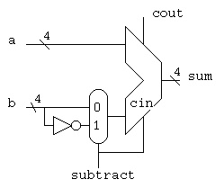 When the signal "subtract" is '1' the circuit subtracts 'b' from 'a'.
When the signal "subtract" is '0' the circuit adds 'a' to 'b'.
The basic circuit is written for VHDL as:
a4: entity work.add4 port map(a, b_mux, subtract, sum, cout);
i4: b_bar <= not b;
m4: entity work.mux4 port map(b, b_bar, subtract, b_mux);
The general rule is that each circuit component symbol on
a schematic diagram will become one VHDL statement.
There are many other VHDL statements needed to run a complete
simulation.
The annotated output of the simulation is:
subtract=0, a=0100, b=0010, sum=0110 4+2=6
subtract=1, a=0100, b=0010, sum=0010 4-2=2
subtract=0, a=1100, b=0010, sum=1110 (-4)+2=(-2)
subtract=1, a=1100, b=0010, sum=1010 (-4)-2=(-6)
subtract=0, a=1100, b=1110, sum=1010 (-4)+(-2)=(-6)
subtract=1, a=1100, b=1110, sum=1110 (-4)-(-2)=(-2)
subtract=0, a=0011, b=1110, sum=0001, 3+(-2)=1
subtract=1, a=0011, b=1110, sum=0101, 3-(-2)=5
The full VHDL code is sub4.vhdl
The run file is sub4.run
The full output file is sub4.out
A fragment of the Makefile is Makefile.sub4
Somewhat similar Verilog code, using 4 bit mux
sub4.v
sub4_v.out
Checking both add and subtract:
sub4.v running
add
a=1011, b=1000, cin=1, sum=0100, cout=1
in0=1000, in1=0111, ctl=0, b=1000
subtract
a=1011, b=0111, cin=1, sum=0011, cout=1
in0=1000, in1=0111, ctl=1, b=0111
add
a=0000, b=0000, cin=0, sum=0000, cout=0
in0=0000, in1=1111, ctl=0, b=0000
subtract
a=0000, b=1111, cin=0, sum=1111, cout=0
in0=0000, in1=1111, ctl=1, b=1111
add
a=1111, b=1111, cin=1, sum=1111, cout=1
in0=1111, in1=0000, ctl=0, b=1111
subtract
a=1111, b=0000, cin=1, sum=0000, cout=1
in0=1111, in1=0000, ctl=1, b=0000
L113 "sub4.v": $finish at simulation time 30
When the signal "subtract" is '1' the circuit subtracts 'b' from 'a'.
When the signal "subtract" is '0' the circuit adds 'a' to 'b'.
The basic circuit is written for VHDL as:
a4: entity work.add4 port map(a, b_mux, subtract, sum, cout);
i4: b_bar <= not b;
m4: entity work.mux4 port map(b, b_bar, subtract, b_mux);
The general rule is that each circuit component symbol on
a schematic diagram will become one VHDL statement.
There are many other VHDL statements needed to run a complete
simulation.
The annotated output of the simulation is:
subtract=0, a=0100, b=0010, sum=0110 4+2=6
subtract=1, a=0100, b=0010, sum=0010 4-2=2
subtract=0, a=1100, b=0010, sum=1110 (-4)+2=(-2)
subtract=1, a=1100, b=0010, sum=1010 (-4)-2=(-6)
subtract=0, a=1100, b=1110, sum=1010 (-4)+(-2)=(-6)
subtract=1, a=1100, b=1110, sum=1110 (-4)-(-2)=(-2)
subtract=0, a=0011, b=1110, sum=0001, 3+(-2)=1
subtract=1, a=0011, b=1110, sum=0101, 3-(-2)=5
The full VHDL code is sub4.vhdl
The run file is sub4.run
The full output file is sub4.out
A fragment of the Makefile is Makefile.sub4
Somewhat similar Verilog code, using 4 bit mux
sub4.v
sub4_v.out
Checking both add and subtract:
sub4.v running
add
a=1011, b=1000, cin=1, sum=0100, cout=1
in0=1000, in1=0111, ctl=0, b=1000
subtract
a=1011, b=0111, cin=1, sum=0011, cout=1
in0=1000, in1=0111, ctl=1, b=0111
add
a=0000, b=0000, cin=0, sum=0000, cout=0
in0=0000, in1=1111, ctl=0, b=0000
subtract
a=0000, b=1111, cin=0, sum=1111, cout=0
in0=0000, in1=1111, ctl=1, b=1111
add
a=1111, b=1111, cin=1, sum=1111, cout=1
in0=1111, in1=0000, ctl=0, b=1111
subtract
a=1111, b=0000, cin=1, sum=0000, cout=1
in0=1111, in1=0000, ctl=1, b=0000
L113 "sub4.v": $finish at simulation time 30
Lecture 20 Multiply and divide
Multiplication and division are taught in elementary school, yet
they are still being worked on for computer applications.
The earliest computers just provided add and subtract with
conditional Branch, leaving the programmer to write multiply
and divide subroutines.
Early computers used bit-serial methods that required about
N squared clock times for multiplying or dividing N-bit numbers.
With a parallel adder, the time for multiply was reduced to
N/2 clock times (Booth algorithm) and division N clock times.
Todays computers use parallel, combinational, circuits for
multiply and divide. These circuits still take too long for
signals to propagate in one clock time. The combinational
circuits are "pipelined" so that a multiply or divide can be
completed every clock time.
Consider multiplying unsigned numbers 1010 * 1100 (10 times 12)
Using a hand method would produce:
1010
* 1100
---------
0000 <- think of the multiplier bit being "anded" with
0000 the multiplicand. A 1-bit "and" in digital logic
1010 is like a 1-bit "multiply".
1010
---------
01111000 4-bits times 4-bits produces an 8-bit product
When adding by hand, we can add the middle columns four bits and
produce a sum bit and possibly a carry. In hardware the number
of input bits is fixed. From the previous lecture, we could use
four 4-bit adders with additional "and" gates to do the multiply.
A better design incorporates the "and" gate to do a 1-bit multiply
inside the previous lectures full adder. With this single building
block, that is easy to replicate many times, we get the following
parallel multiplier design.
The 4-bit by 4-bit multiply to produce an 8-bit unsigned product is
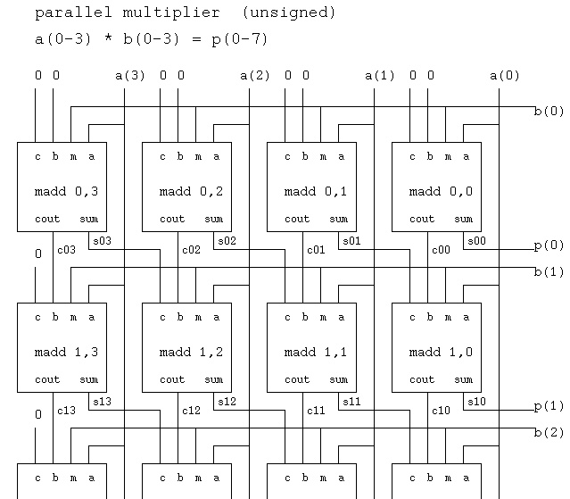
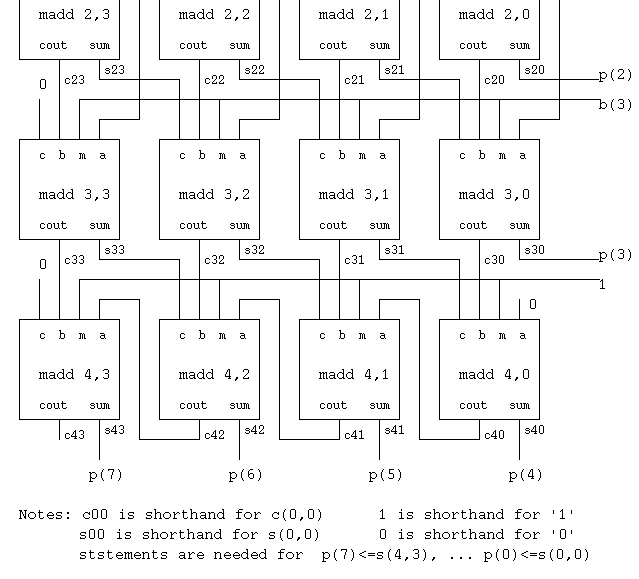 The component madd circuit is
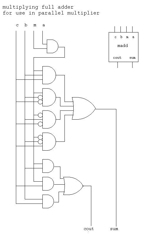
VHDL implementation is
The VHDL source code is pmul4.vhdl
The VHDL test driver is pmul4_test.vhdl
The VHDL output is pmul4_test.out
The Cadence run file is pmul4_test.run
The partial Makefile is Makefile.pmul4_test
Verilog implementation is
The Verilog source code is mul4.v
The Verilog output is mul4_v.out
Notice that the only component used to build the multiplier
is "madd" and some uses of "madd" have constants as inputs.
It is technology dependent whether the same circuit is used
or specialized, minimized, circuits are substituted.
Division is performed by using subtraction. A sample unsigned binary
division of an 8-bit dividend by a 4-bit divisor that produces
a 4-bit quotient and 4-bit remainder is:
1010 <- quotient
/---------
1100/ 01111011 <- dividend
-1100
-----
0110
-0000
------
1101
-1100
------
0011
-0000
-----
0011 <- remainder
With a parallel adder and a double length register, serial division
can be performed. Conventional division requires a trial subtraction
and possibly a restore of the partial remainder. A non restoring
serial division requires N clock times for a N-bit divisor.
The schematic for a parallel 8-bit dividend divided by 4-bit divisor
to produce an 4-bit quotient and 4-bit remainder is:
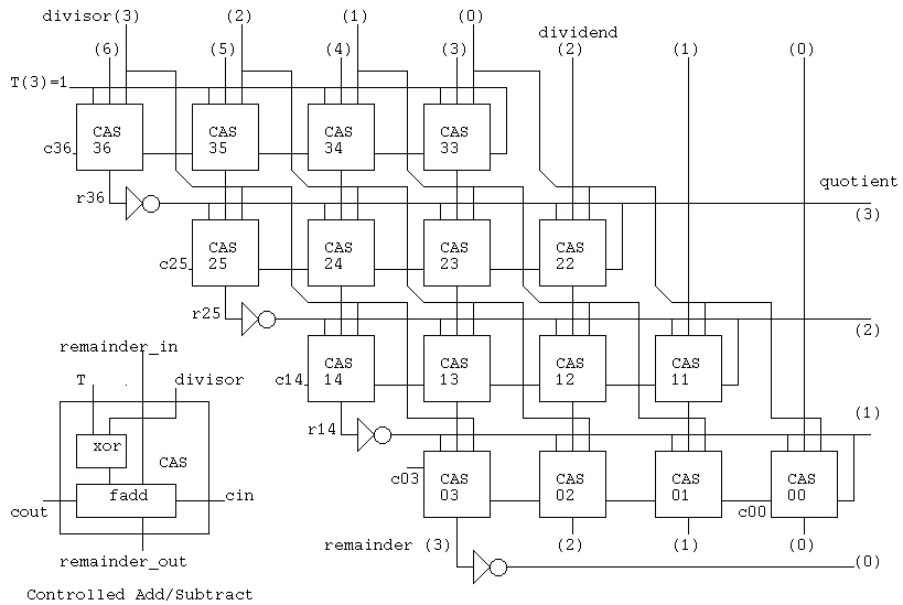 Notice that the building block is similar to the 'madd' component
in the parallel multiplier. The 'cas' component is the same full
adder with an additional xor gate.
The VHDL test driver is divcas4_test.vhdl
The VHDL output is divcas4_test.out
The Cadence run file is divcas4_test.run
The partial Makefile is Makefile.divcas4_test
The Verilog code is div4.v
The Verilog output is div4_v.out
Divide can create on overflow condition. This is typically handled by
separate logic in order to keep the main circuit neat. There is a
one bit preshift of the dividend in the manual, serial and parallel
division. Thus, no dividend bit number seven appears on the parallel
schematic.
Notice that the building block is similar to the 'madd' component
in the parallel multiplier. The 'cas' component is the same full
adder with an additional xor gate.
The VHDL test driver is divcas4_test.vhdl
The VHDL output is divcas4_test.out
The Cadence run file is divcas4_test.run
The partial Makefile is Makefile.divcas4_test
The Verilog code is div4.v
The Verilog output is div4_v.out
Divide can create on overflow condition. This is typically handled by
separate logic in order to keep the main circuit neat. There is a
one bit preshift of the dividend in the manual, serial and parallel
division. Thus, no dividend bit number seven appears on the parallel
schematic.
Project 4 is assigned
Lecture 21 Karnaugh maps, Quine McClusky
Notice Homework 4 had instruction to not minimize, thus many points
lost. Relates to this lecture.
GHDL and IVERILOG now available on linux.gl.umbc.edu.
Thus do project 4 and project 5 using given Makefile's.
A Karnaugh map, K-map, is a visual representation of a Boolean function.
The plan is to recognize patterns in the visual representation and
thus find a minimized circuit for the Boolean function.
There is a specific labeling for a Karnaugh map for each number
of circuit input variables. A Karnaugh map consists of squares where
each square represents a minterm. Notice that only one variable can
change in any adjacent horizontal or vertical square. Remember that
a minterm is the input pattern where there is a '1' in the output
of a truth table. (Covered in HW4)
After the map is drawn and labeled, a '1' is placed in each square
corresponding to a minterm of the function. Later an 'X' will be
allowed for "don't care" minterms. By convention, no zeros are
written into the map.
Having a filled in map, visual skills and intuition are used to
find the minimum number of rectangles that enclose all the ones.
The rectangles must have sides that are powers of two. No
rectangle is allowed to contain a blank square. The map is a toroid
such that the top row is logically adjacent to the bottom row and
the right column is logically adjacent to the left column. Thus
rectangles do not have to be within the two dimensional map.
The resulting minimized boolean function is written as a sum of
products. Each rectangle represents a product, "and" gate, and
the products are summed, "or gate", to produce the result. A rectangle
that contains both a variable and its complement does not have
that variable in the product term, omit the variable as an input
to the "and" gate.
Basic labeling Minterm numbers Minterms
B=0 B=1 B=0 B=1 B=0 B=1
+---+---+ +---+---+ +---+---+
A=0 | | | A=0 |m0 |m1 | A=0 |__ |_ |
+---+---+ +---+---+ |AB |AB |
A=1 | | | A=1 |m2 |m3 | +---+---+
+---+---+ +---+---+ A=1 | _ | |
|AB |AB |
+---+---+
Truth table Karnaugh map Covering with rectangles
A B | F B=0 B=1 B=0 B=1
----+-- +---+---+ +-----+-----+
0 0 | 0 A=0 | | 1 | | |+---+|
0 1 | 1 m1 +---+---+ A=0 | || 1 ||
1 0 | 1 m2 A=1 | 1 | | | |+---+|
1 1 | 0 +---+---+ +-----+-----+
|+---+| |
A=1 || 1 || |
|+---+| |
+-----+-----+
_ _
Minimized function F = AB + AB
Note: For each covering rectangle, there will be exactly one
product term in the final equation for the function.
Find the variable(s) that are both 1 and 0 in the rectangle.
Such variables will not appear in the product term. Take any
minterm from the covering rectangle, replace 1 with the variable,
replace 0 with the complement of the variable. Cross out the
variables that do not appear. The result is exactly one product
term needed by the final equation of the function.
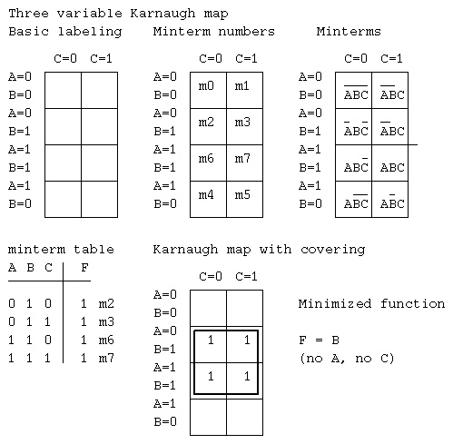
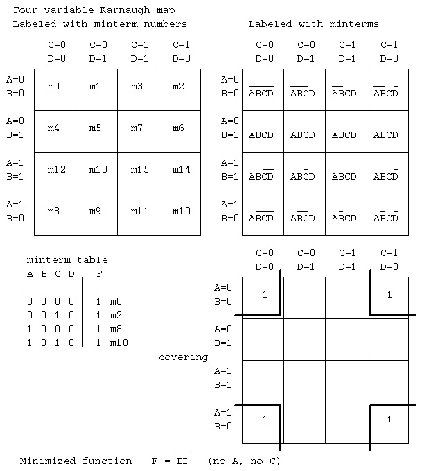 It is possible to have minterms that are don't care. For these
minterms, place an "X" or "-" in the Karnaugh map rather than
a one. The covering follows the obvious extended rule.
Covering rectangles may include any don't care squares.
Covering rectangles do not have to include don't care squares.
No rectangle can enclose only don't care squares.
It is possible to have minterms that are don't care. For these
minterms, place an "X" or "-" in the Karnaugh map rather than
a one. The covering follows the obvious extended rule.
Covering rectangles may include any don't care squares.
Covering rectangles do not have to include don't care squares.
No rectangle can enclose only don't care squares.
Quine McClusky minimization
A tabular algorithm for producing the minimum two level sum of products
is know as the Quine McClusky method.

You may download and build the software that performs this minimization.
qm.tgz or link to a Linux executable
ln -s /afs/umbc.edu/users/s/q/squire/pub/download/qm qm

The man page, qm.1 , is in the same directory.

The algorithm may be performed manually using the following steps:
Remember: the minterms are the inputs from a truth table where output is 1
Also:     the minterms are inputs to "and" gates in an "and" "or" circuit
          unused inputs into each "and" gate get an X
          used inputs get a 1, complemented inputs get a 0

1) Have available the minterms of the function to be minimized.
   There may be X's for don't care cases.

2) Create groups of minterms, starting with the minterms with the
   fewest number of ones.
   All minterms in a group must have the same number of ones and
   if any X's, the X's must be in the same position. There may be
   some groups with only one minterm.

3) Create new minterms by combining minterms from groups that
   differ by a count of one. Two minterms are combined if they
   differ in exactly one position. Place an X in that position
   of the newly created minterm. Mark the minterms that are
   used in combining (they will be deleted at the end of this step).
   Basically, take the first minterm from the first group. Compare
   this minterm to all minterms in the next group(s) that have
   one additional one. Repeat working until the last group is reached.

4) Delete the marked minterms.

5) Repeat steps 2) 3) and 4) until no more minterms are combined.

6) The minimized function is the remaining minterms, deleting any
   X's.

Example:
1) Given the minterms
  A B C D | F
  --------+--
  0 0 0 0 | 1  m0
  0 0 1 0 | 1  m2
  1 0 0 0 | 1  m8
  1 0 1 0 | 1  m10

2) Create groups
   m0  0 0 0 0   count of 1's is 0
       -------
   m2  0 0 1 0   count of 1's is 1
   m8  1 0 0 0
       -------
   m10 1 0 1 0   count of 1's is 2

3) Create new minterms by combining
   Compare all in first group to all in second group
   m0 to m2  0 0 0 0
             0 0 1 0
             =======  they differ in one position
             0 0 X 0  combine and put an X in that position

   m0 to m8  0 0 0 0
             1 0 0 0
             =======  they differ in one position
             X 0 0 0  combine and put an X in that position

  Compare all in second group to all in third group
  m2 to m10  0 0 1 0
             1 0 1 0
             =======  they differ in one position
             X 0 1 0  combine and put an X in that position

  m8 to m10  1 0 0 0
             1 0 1 0
             =======  they differ in one position
             1 0 X 0  combine and put an X in that position

  no more candidates to compare.

4) Delete marked minterms (those used in any combining)
   (do not keep duplicates) Thus the minterms are now:
   0 0 X 0
   X 0 0 0
   X 0 1 0
   1 0 X 0

2) Repeat grouping (technically there are four groups, although
   the number of ones is either zero or one).
   0 0 X 0
   -------
   X 0 0 0
   -------
   X 0 1 0
   -------
   1 0 X 0

3) Create new minterms by combining
   0 0 X 0
   1 0 X 0  any X's must be the same in both
   =======  they differ in one position
   X 0 X 0  combine and put an X in that position

   X 0 0 0
   X 0 1 0
   =======  they differ in one position
   X 0 X 0  combine and put an X in that position

4) Delete marked minterms (those used in any combining)
   (do not keep duplicates) Thus the minterms are now:
   X 0 X 0

5) No more combining is possible.

6) The minimized function is the remaining minterms, deleting any
   X's. All remaining minterms are prime implicants

   A B C D            __
   X 0 X 0   thus F = BD

In essence, the Quine McClusky algorithm is doing the same
operations as the Karnaugh map. The difference is that no guessing
is used in the Quine McClusky algorithm and "qm" as it is called,
can be (and has been) implemented as a computer program.

A final note on labeling:
It does not matter what names are used for variables.
It does not matter in what order variables are used.
It does not matter if "-" or "X" is used for don't care.
It is important to keep a consistent relation between the bit
positions in minterms and the order of variables.

You may download and build the software that performs this minimization.
qm.tgz or link to a Linux executable
ln -s /afs/umbc.edu/users/s/q/squire/pub/download/qm qm

The man page, qm.1 , is in the same directory.


Sample  Makefile, input data, output minterms, equation

all: eqn5.eqn

eqn5.eqn: eqn5.dat
	qm -n 5 -m -i eqn5.dat -o eqn5.eqn > eqn5.min
	cat eqn5.min
	cat eqn5.eqn

input  eqn5.dat  is
0 1 0 0 1
0 1 1 0 1
1 0 0 0 0
1 0 0 1 0
1 1 0 0 0
1 1 0 1 0
1 1 0 0 1
1 1 1 0 1

output  eqn5.min  is
Quine McClusky digital circuit minimization V1.0
final prime implicants
gr a b c d e  cv
0  1 - 0 - 0  0
0  - 1 - 0 1  0
0  1 1 0 0 -  0


output  eqn5.eqn  is  (VHDL version, Verilog version)
out <=
  (    a           and not c           and not e ) or
  (              b           and not d and     e ) or
  (    a and     b and not c and not d           );

out =
  ( a      & ~c      & ~e ) |
  (      b      & ~d &  e ) |
  ( a &  b & ~c & ~d      );


More information is at Simulators and parsers

Homework 6 is assigned
eight by eight Karnaugh Map  one bit change each way
      def
      000  001   011   010   110   111   101   100  last 3 bits
abc  _____________________________________________
000 |  1 |     |     |     |     |     |     |    |
     _____________________________________________
001 |    |     |     |     |     |     |     |    |
     _____________________________________________
011 |    |     |     |     |     |     |     |    |
     _____________________________________________
010 |    |     |     |     |     |     |     |    |
     _____________________________________________
110 |    |     |     |     |     |     |     |    |
     _____________________________________________
111 |    |     |     |     |     |     |     |    |
     _____________________________________________
101 |    |     |     |     |     |     |     |    |
     _____________________________________________
100 |    |     |     |     |     |     |     |  1 |
     _____________________________________________

first
three
bits

first and last minterm shown  1
Lecture 22 Flip flops, latches, registers
We now focus on sequential logic. Logic with storage and state.
The previous lectures were on combinational logic, gates.
In order to build very predictable large digital logic systems,
synchronous design is used. A synchronous system has a special
signal called a master clock. The clock signal continuously
has values 0101010101010 ... . This is usually just a square
wave generator at some frequency. A clock with frequency 1 GHz
has a period of 1 ns. Half of the period the clock is a logical 1
and the other half of the clock period the clock is a logical 0.
___ ___ ___
clk ___| |___| |___|
|< 1 ns>|
The VHDL code fragment to generate the clk signal is:
signal clk : std_logic := '0';
begin
clk <= not clk after 500 ps;
A synchronous system is designed with registers that input a
value on a raising clock edge, hold the signal until the next
raising clock edge. The designer must know the timing of
combinational logic because the signals must propagate through
the combinational logic in less than a clock time.
Combinational logic can not have loops or feedback.
Sequential logic is specifically designed to allow loops and
feedback. The design rule is that and loop or feedback must
include a storage element (register) that is clocked.
+------------------------------------+
| |
| +---------------+ +----------+ |
+->| combinational |-->| register |--+
| logic | | |
+---------------+ +----------+
^
| clock signal
A register may be many bits and each bit is built from a flip flop.
A flip flop is ideally either in a '1' state or a '0' state.
The most primitive flip flop is called a latch. A latch can be made
from two cross coupled nand gates. The latch is not easy to work
with in large circuits, thus JK flip flops and D flip flops are
typically used. In modern large scale integrated circuits, the
flip flops and thus the registers are designed at the device level.
A classical model of a JK flip flop is
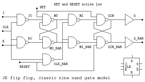 On the raising edge of the clock signal,
if J='1' the Q output is set to '1'
if K='1' the Q output is set to '0'
if both J and K are '1', the Q signal is inverted.
Note that Q_BAR is the complement of Q in the steady state.
There is a transient time when both could be '1' or both could be '0'.
The SET signal is normally '1' yet can be set to '0' for a short
time in order to force Q='1' (set the flip flop).
The RESET signal is normally '1' yet can be set to '0' for a short
time in order to force Q='0' (reset the flip flop or register to zero).
A slow counter, called a ripple counter, can be made from JK flip
flops using the following circuit:
On the raising edge of the clock signal,
if J='1' the Q output is set to '1'
if K='1' the Q output is set to '0'
if both J and K are '1', the Q signal is inverted.
Note that Q_BAR is the complement of Q in the steady state.
There is a transient time when both could be '1' or both could be '0'.
The SET signal is normally '1' yet can be set to '0' for a short
time in order to force Q='1' (set the flip flop).
The RESET signal is normally '1' yet can be set to '0' for a short
time in order to force Q='0' (reset the flip flop or register to zero).
A slow counter, called a ripple counter, can be made from JK flip
flops using the following circuit:
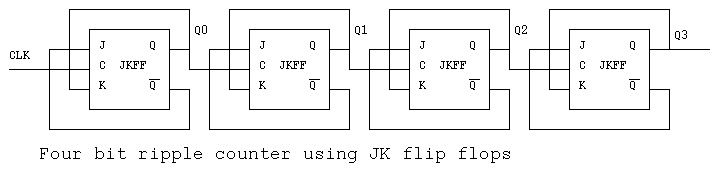 The VHDL source code for the entity JKFF, the JK flip flop,
and the four bit ripple counter is jkff_cntr.vhdl
The Cadence run file is jkff_cntr.run
The Cadence output file is jkff_cntr.out
ncsim: 04.10-s017: (c) Copyright 1995-2003 Cadence Design Systems, Inc.
ncsim> run 340 ns
q3, q2, q1, q0 q3_ q2_ q1_ q0_ clk
0 0 0 0 1 1 1 1 1 at 10 NS
0 0 0 1 1 1 1 0 1 at 30 NS
0 0 1 0 1 1 0 1 1 at 50 NS
0 0 1 1 1 1 0 0 1 at 70 NS
0 1 0 0 1 0 1 1 1 at 90 NS
0 1 0 1 1 0 1 0 1 at 110 NS
0 1 1 0 1 0 0 1 1 at 130 NS
0 1 1 1 1 0 0 0 1 at 150 NS
1 0 0 0 0 1 1 1 1 at 170 NS
1 0 0 1 0 1 1 0 1 at 190 NS
1 0 1 0 0 1 0 1 1 at 210 NS
1 0 1 1 0 1 0 0 1 at 230 NS
1 1 0 0 0 0 1 1 1 at 250 NS
1 1 0 1 0 0 1 0 1 at 270 NS
1 1 1 0 0 0 0 1 1 at 290 NS
1 1 1 1 0 0 0 0 1 at 310 NS
0 0 0 0 1 1 1 1 1 at 330 NS
________________________________________________________________
reset
_ _ _ _ _ _ _ _ _ _ _ _ _ _ _ _
clk | |_| |_| |_| |_| |_| |_| |_| |_| |_| |_| |_| |_| |_| |_| |_| |_
___ ___ ___ ___ ___ ___ ___ ___
q0 ___| |___| |___| |___| |___| |___| |___| |___| |
_______ _______ _______ _______
q1 _______| |_______| |_______| |_______| |
_______________ _______________
q2 _______________| |_______________| |
_______________________________
q3 _______________________________| |
Ran until 340 NS + 0
ncsim> exit
In many designs, only one input is needed and the resulting flip flop
is a D flip flop. A D flip flop needs 6 nand gates rather than the
9 nand gates needed by the JK flip flop. There is a proportional
reduction is devices when the flip flop is designed from basic
transistors.
The VHDL source code for the entity JKFF, the JK flip flop,
and the four bit ripple counter is jkff_cntr.vhdl
The Cadence run file is jkff_cntr.run
The Cadence output file is jkff_cntr.out
ncsim: 04.10-s017: (c) Copyright 1995-2003 Cadence Design Systems, Inc.
ncsim> run 340 ns
q3, q2, q1, q0 q3_ q2_ q1_ q0_ clk
0 0 0 0 1 1 1 1 1 at 10 NS
0 0 0 1 1 1 1 0 1 at 30 NS
0 0 1 0 1 1 0 1 1 at 50 NS
0 0 1 1 1 1 0 0 1 at 70 NS
0 1 0 0 1 0 1 1 1 at 90 NS
0 1 0 1 1 0 1 0 1 at 110 NS
0 1 1 0 1 0 0 1 1 at 130 NS
0 1 1 1 1 0 0 0 1 at 150 NS
1 0 0 0 0 1 1 1 1 at 170 NS
1 0 0 1 0 1 1 0 1 at 190 NS
1 0 1 0 0 1 0 1 1 at 210 NS
1 0 1 1 0 1 0 0 1 at 230 NS
1 1 0 0 0 0 1 1 1 at 250 NS
1 1 0 1 0 0 1 0 1 at 270 NS
1 1 1 0 0 0 0 1 1 at 290 NS
1 1 1 1 0 0 0 0 1 at 310 NS
0 0 0 0 1 1 1 1 1 at 330 NS
________________________________________________________________
reset
_ _ _ _ _ _ _ _ _ _ _ _ _ _ _ _
clk | |_| |_| |_| |_| |_| |_| |_| |_| |_| |_| |_| |_| |_| |_| |_| |_
___ ___ ___ ___ ___ ___ ___ ___
q0 ___| |___| |___| |___| |___| |___| |___| |___| |
_______ _______ _______ _______
q1 _______| |_______| |_______| |_______| |
_______________ _______________
q2 _______________| |_______________| |
_______________________________
q3 _______________________________| |
Ran until 340 NS + 0
ncsim> exit
In many designs, only one input is needed and the resulting flip flop
is a D flip flop. A D flip flop needs 6 nand gates rather than the
9 nand gates needed by the JK flip flop. There is a proportional
reduction is devices when the flip flop is designed from basic
transistors.
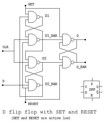 The VHDL source code for the entity DFF, the D flip flop,
and the four bit counter is dff_cntr.vhdl
The Cadence run file is dff_cntr.run
The Cadence output file is dff_cntr.out
The VHDL source code for the D flip flops:
dff.vhdl
Entity dff1 is five nand model
Entity dff2 is six nand model
The Cadence run file is dff.run
The Cadence output file is dff.out
Similar Verilog source code
dff.v
test_dff.v
test_dff_v.out
The D flip flop ripple counter
The VHDL source code for the entity DFF, the D flip flop,
and the four bit counter is dff_cntr.vhdl
The Cadence run file is dff_cntr.run
The Cadence output file is dff_cntr.out
The VHDL source code for the D flip flops:
dff.vhdl
Entity dff1 is five nand model
Entity dff2 is six nand model
The Cadence run file is dff.run
The Cadence output file is dff.out
Similar Verilog source code
dff.v
test_dff.v
test_dff_v.out
The D flip flop ripple counter
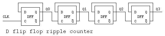
Lecture 23 Sequential Logic
Sequential logic can be represented as three equivalent forms:
State Transition Table, State Transition Diagram and logic circuit.
A State is given a name, we use A, B, C for this discussion, yet
meaningful names are better. A machine or sequential logic circuit
can be in only one state at a time. We are assuming synchronous
logic where all flip flops are clocked by the same clock signal.
The input signal is assumed to be available just before each clock
transition. Optionally, the arrival of an input can also cause the
clock to have one pulse.
Two possible forms of State Transition Table are:
Input state state
| 0 | 1 Input
--+---+--- A 0 B
state A | B | C A 1 C
B | C | B B 0 C
C | C | A B 1 B
C 0 C
C 1 A
The meaning of both tables is:
When in state A with input 0 transition to state B
When in state A with input 1 transition to state C
When in state B with input 0 transition to state C
When in state B with input 1 stay in state B
etc.
The exact same information can be presented as a
State Transition Diagram.
 The meaning is the same:
When in state A with input 0 transition to state B
When in state A with input 1 transition to state C
When in state B with input 0 transition to state C
When in state B with input 1 stay in state B
etc.
To convert either a State Transition Table or Diagram to
a circuit, assign a D flip flop to each state. The "q" output
of the flip flop is assigned the signal name of the state.
The "d" input of the flip flop is assigned a signal name
of the state concatenated with "in".
Write the combinational logic equations for each state
input from observing the "to" state in the transition table
or diagram.
For this sequential machine, using I as the input
Ain <= (C and I); -- C transitions to A when I='1'
Bin <= (A and not I) or -- A transitions to B when I='0'
(B and I); -- B transitions to B when I='1'
Cin <= (A and I) or -- A transitions to C when I='1'
(B and not I) or -- B transitions to C when I='0'
(C and not I); -- C transitions to C when I='0'
The partial circuit is shown below.
Implied is a set signal to A and reset signals to
B and C for the initial or start condition.
Implied is a common clock signal to all flip flops.
The meaning is the same:
When in state A with input 0 transition to state B
When in state A with input 1 transition to state C
When in state B with input 0 transition to state C
When in state B with input 1 stay in state B
etc.
To convert either a State Transition Table or Diagram to
a circuit, assign a D flip flop to each state. The "q" output
of the flip flop is assigned the signal name of the state.
The "d" input of the flip flop is assigned a signal name
of the state concatenated with "in".
Write the combinational logic equations for each state
input from observing the "to" state in the transition table
or diagram.
For this sequential machine, using I as the input
Ain <= (C and I); -- C transitions to A when I='1'
Bin <= (A and not I) or -- A transitions to B when I='0'
(B and I); -- B transitions to B when I='1'
Cin <= (A and I) or -- A transitions to C when I='1'
(B and not I) or -- B transitions to C when I='0'
(C and not I); -- C transitions to C when I='0'
The partial circuit is shown below.
Implied is a set signal to A and reset signals to
B and C for the initial or start condition.
Implied is a common clock signal to all flip flops.
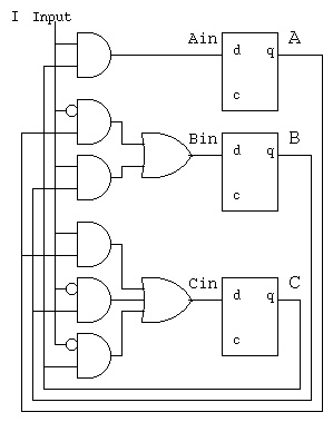 Not shown is the output(s) that may be any combinational
circuit, function, of the input and states.
e.g. out <= (A and I) or (B and not I);
There is an algorithm and corresponding computer program for
minimizing the State Transition Table,
see Myhill Nerode minimization.
There is an algorithm and corresponding computer program for
minimizing the combinational logic
are Quine McClusky minimization.
One application of sequential logic is for garage door openers
or car door locks. The basic sequential logic is a spin lock.
This circuit has the property of eventually detecting the
specific sequence it is designed to accept. The transmitter may
start anywhere in the sequence and continue to repeat the sequence
until the receiver detects the specific sequence.
Not shown is the output(s) that may be any combinational
circuit, function, of the input and states.
e.g. out <= (A and I) or (B and not I);
There is an algorithm and corresponding computer program for
minimizing the State Transition Table,
see Myhill Nerode minimization.
There is an algorithm and corresponding computer program for
minimizing the combinational logic
are Quine McClusky minimization.
One application of sequential logic is for garage door openers
or car door locks. The basic sequential logic is a spin lock.
This circuit has the property of eventually detecting the
specific sequence it is designed to accept. The transmitter may
start anywhere in the sequence and continue to repeat the sequence
until the receiver detects the specific sequence.
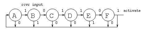 state | input from rcvr
| 0 | 1 |
------+---+---+
A | A | B |
B | C | A |
C | A | D |
D | A | E |
E | F | A |
F | A | A activate signal
This "spin lock" is designed to accept the sequence 101101.
A logic circuit, by inspection of the state transition table
using I for input from rcvr, DFF outputs are DFF name,
DFF D input is DFF name with "in".
Ain = (~I&A)|(I&B)|(~I&C)|(~I&D)|(I&E)|F
Bin = ( I&A)
Cin = (~I&B)
Din = (I&C)
Ein = (I&D)
Fin = (~I&E)
state | input from rcvr
| 0 | 1 |
------+---+---+
A | A | B |
B | C | A |
C | A | D |
D | A | E |
E | F | A |
F | A | A activate signal
This "spin lock" is designed to accept the sequence 101101.
A logic circuit, by inspection of the state transition table
using I for input from rcvr, DFF outputs are DFF name,
DFF D input is DFF name with "in".
Ain = (~I&A)|(I&B)|(~I&C)|(~I&D)|(I&E)|F
Bin = ( I&A)
Cin = (~I&B)
Din = (I&C)
Ein = (I&D)
Fin = (~I&E)
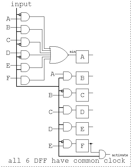 A transmitter could be designed to send the specific sequence
followed by an equal number of zero bits then repeat the
specific sequence. (Assuming the first bit of the sequence is a '1')
An all zero code is not useful.
More sophisticated spin locks will change the sequence that is
detected each time a sequence is accepted. The transmitter must then
send a family of sequences because, in general, the transmitter
will not know what the receivers sequence setting is. A method
of handling this unknown is to have the receiver change to a
pseudo random setting of some of the bit positions. The
transmitter then generates and transmits all of the pseudo random
patterns in the correct bit positions. Sample pseudo random
sequence generators are shown below.
A maximal length pseudo random sequence generator can generate
2^n -1 unique patterns with an n-bit shift register. For each
number of shift register stages there are one or more feedback
circuits using just exclusive-or to compute the next input bit.
The output may be n-bit patterns, a2, a1. a0 in the circuit below.
The output may also be a bit stream taken from just a0 or a2.
The basic shift register is clocked at some frequency. Bits shift
left to right one position per clock. The top bit is inserted
based on the feedback into the exclusive-or gate(s).
A sequence, starting with the "seed" 0 0 1 is shown below:
A transmitter could be designed to send the specific sequence
followed by an equal number of zero bits then repeat the
specific sequence. (Assuming the first bit of the sequence is a '1')
An all zero code is not useful.
More sophisticated spin locks will change the sequence that is
detected each time a sequence is accepted. The transmitter must then
send a family of sequences because, in general, the transmitter
will not know what the receivers sequence setting is. A method
of handling this unknown is to have the receiver change to a
pseudo random setting of some of the bit positions. The
transmitter then generates and transmits all of the pseudo random
patterns in the correct bit positions. Sample pseudo random
sequence generators are shown below.
A maximal length pseudo random sequence generator can generate
2^n -1 unique patterns with an n-bit shift register. For each
number of shift register stages there are one or more feedback
circuits using just exclusive-or to compute the next input bit.
The output may be n-bit patterns, a2, a1. a0 in the circuit below.
The output may also be a bit stream taken from just a0 or a2.
The basic shift register is clocked at some frequency. Bits shift
left to right one position per clock. The top bit is inserted
based on the feedback into the exclusive-or gate(s).
A sequence, starting with the "seed" 0 0 1 is shown below:
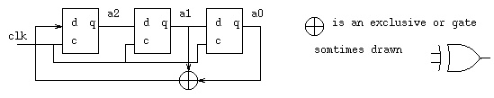 0 0 1
1 0 0
0 1 0
1 0 1
1 1 0
1 1 1
0 1 1
0 0 1
Notice the 2^3 -1 = 7 unique patterns and then the repeat.
A maximal length pseudo random shift register for 5-bit patterns is
shown in typical abbreviated schematic form.
0 0 1
1 0 0
0 1 0
1 0 1
1 1 0
1 1 1
0 1 1
0 0 1
Notice the 2^3 -1 = 7 unique patterns and then the repeat.
A maximal length pseudo random shift register for 5-bit patterns is
shown in typical abbreviated schematic form.
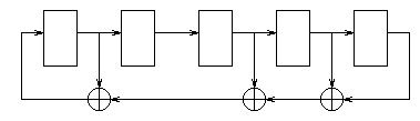 With a seed of 0 0 0 0 1 the next few values are
1 0 0 0 0
1 1 0 0 0
1 1 1 0 0
0 1 1 1 0
The full output sequence with bits reversed
Maximal length pseudo random sequences may be generated for
any length. Below in short hand notation is the feedback paths
for many lengths up to 32.
/* length bits(high order first) of h[], right is h[0]
* 2 1 1 1 top bit always one, the input to msb stage
* 3 1 0 1 1 bottom bit always one, output of lsb stage
* 4 1 0 0 1 1 x(4)= x^1+x^0 x^0=1 initially
* 5 1 1 0 1 1 1 x(5)=x^4+x^2+x^1+x^0 x^0=1 initially
* 6 1 0 0 0 0 1 1 + is exclusive or
* 7 1 1 1 1 0 1 1 1 x^0 is rightmost bit
* 8 1 1 1 1 0 0 1 1 1 x^1 is next bit, etc.
* 9 1 1 1 0 0 0 1 1 1 1
* 10 1 1 0 0 1 1 1 1 1 1 1
* 11 1 1 0 1 1 0 0 1 1 1 1 1
* 12 1 1 0 0 0 1 0 0 1 0 1 1 1
* 13 1 1 0 0 0 1 1 1 1 1 1 1 1 1
* 14 1 1 0 1 0 0 0 1 1 1 1 1 1 1 1
* 15 1 1 0 1 0 0 0 1 1 0 1 1 1 1 1 1
* 16 1 1 0 1 1 0 0 0 0 0 1 1 1 1 1 1 1
* 18 1 1 1 1 0 0 0 0 1 1 0 0 0 1 1 0 0 0 1
* 20 1 1 0 0 0 0 0 0 0 0 0 0 0 0 0 0 1 1 0 0 1
* 24 1 0 0 0 0 0 0 0 0 0 0 0 0 0 0 0 0 1 0 0 0 0 1 1 1
* 30 1 0 0 0 0 0 0 1 0 0 0 0 0 0 0 0 0 0 0 0 0 0 0 0 0 0 0 0 1 1 1
* 31 1 0 0 0 1 0 0 0 1 0 0 0 1 0 0 0 1 0 0 0 1 1 1 0 1 1 1 0 1 1 1 1
* 32 1 0 0 0 0 0 1 0 0 1 1 0 0 0 0 0 1 0 0 0 1 1 1 0 1 1 0 1 1 0 1 1 1
*/
project 5 you will finish a spin lock:
see project 5 spin lock.
With a seed of 0 0 0 0 1 the next few values are
1 0 0 0 0
1 1 0 0 0
1 1 1 0 0
0 1 1 1 0
The full output sequence with bits reversed
Maximal length pseudo random sequences may be generated for
any length. Below in short hand notation is the feedback paths
for many lengths up to 32.
/* length bits(high order first) of h[], right is h[0]
* 2 1 1 1 top bit always one, the input to msb stage
* 3 1 0 1 1 bottom bit always one, output of lsb stage
* 4 1 0 0 1 1 x(4)= x^1+x^0 x^0=1 initially
* 5 1 1 0 1 1 1 x(5)=x^4+x^2+x^1+x^0 x^0=1 initially
* 6 1 0 0 0 0 1 1 + is exclusive or
* 7 1 1 1 1 0 1 1 1 x^0 is rightmost bit
* 8 1 1 1 1 0 0 1 1 1 x^1 is next bit, etc.
* 9 1 1 1 0 0 0 1 1 1 1
* 10 1 1 0 0 1 1 1 1 1 1 1
* 11 1 1 0 1 1 0 0 1 1 1 1 1
* 12 1 1 0 0 0 1 0 0 1 0 1 1 1
* 13 1 1 0 0 0 1 1 1 1 1 1 1 1 1
* 14 1 1 0 1 0 0 0 1 1 1 1 1 1 1 1
* 15 1 1 0 1 0 0 0 1 1 0 1 1 1 1 1 1
* 16 1 1 0 1 1 0 0 0 0 0 1 1 1 1 1 1 1
* 18 1 1 1 1 0 0 0 0 1 1 0 0 0 1 1 0 0 0 1
* 20 1 1 0 0 0 0 0 0 0 0 0 0 0 0 0 0 1 1 0 0 1
* 24 1 0 0 0 0 0 0 0 0 0 0 0 0 0 0 0 0 1 0 0 0 0 1 1 1
* 30 1 0 0 0 0 0 0 1 0 0 0 0 0 0 0 0 0 0 0 0 0 0 0 0 0 0 0 0 1 1 1
* 31 1 0 0 0 1 0 0 0 1 0 0 0 1 0 0 0 1 0 0 0 1 1 1 0 1 1 1 0 1 1 1 1
* 32 1 0 0 0 0 0 1 0 0 1 1 0 0 0 0 0 1 0 0 0 1 1 1 0 1 1 0 1 1 0 1 1 1
*/
project 5 you will finish a spin lock:
see project 5 spin lock.
Lecture 24 Computer organization
Below is a schematic of a one clock per instruction computer.
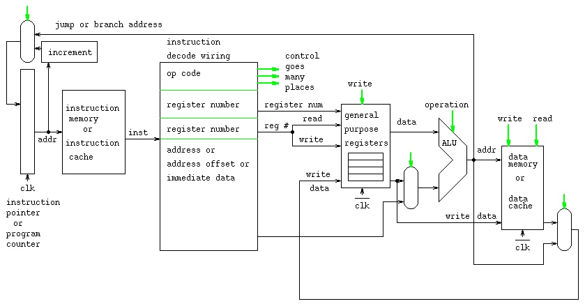 The operation for each instruction is:
The Instruction Pointer Register contains the address of the
next instruction to be executed.
The instruction address goes into the Instruction Memory or
Instruction Cache and the instruction comes out.
"inst" on the diagram.
The Instruction Decode has all the bytes of the instruction:
The instruction has bits for the operation code.
e.g. there is a different bit pattern for add, sub, etc.
Most instructions will reference one register. The register
number has enough bits to select one of the general registers.
Many instructions have a second register. (Not shown here,
on some computers there can be three registers.) The second
(or third) register may be the register number that receives
the result of the operation.
Many instructions have either a memory address for a operand or
a memory offset from a register or immediate data for use by
the operation. This data is passed into the ALU for use by
the operation, either for computing a result or computing
an address.
The general registers receive two register numbers and very
quickly output the data from those two registers.
The ALU receives two data values and control from the
Operation Code part of the instruction. The ALU computes
the value and outputs the value on the line labeled "addr".
This line goes three places: To the mux and possibly into
the Instruction Pointer if the operation is a jump or a branch.
To the Data Memory or Data Cache if the value is a computed
memory address. To the mux that may return the value to a register.
The Data Memory or Data Cache receives an address and write data.
Depending on the control signals "write" and "read":
The Data Memory reads the memory value and send it to the mux.
The Data Memory writes the "write date" into memory at
the memory location "addr".
The final mux may take a value just read from the Data Memory
or Data Cache and return that value to a register or
take the computed value from the ALU and return that value
to a register.
While the above signals are propagating, the Instruction Pointer
is updated by either incrementing by the number of bytes in the
instruction or from the jump or branch address.
This is one instruction, the clock transitions and the next instruction
is started.
The timing consideration that limits the speed of this design is
the long propagation from the new Instruction Pointer value until
the register is written. Notice that the register is written on
clock_bar and the Data Cache is written on clock_bar. Any real
computer must use instruction and data caches for this design
because RAM memory access is slower than logic on the CPU chip.
Another digital logic high level schematic of a CPU:
part1.ps
The operation for each instruction is:
The Instruction Pointer Register contains the address of the
next instruction to be executed.
The instruction address goes into the Instruction Memory or
Instruction Cache and the instruction comes out.
"inst" on the diagram.
The Instruction Decode has all the bytes of the instruction:
The instruction has bits for the operation code.
e.g. there is a different bit pattern for add, sub, etc.
Most instructions will reference one register. The register
number has enough bits to select one of the general registers.
Many instructions have a second register. (Not shown here,
on some computers there can be three registers.) The second
(or third) register may be the register number that receives
the result of the operation.
Many instructions have either a memory address for a operand or
a memory offset from a register or immediate data for use by
the operation. This data is passed into the ALU for use by
the operation, either for computing a result or computing
an address.
The general registers receive two register numbers and very
quickly output the data from those two registers.
The ALU receives two data values and control from the
Operation Code part of the instruction. The ALU computes
the value and outputs the value on the line labeled "addr".
This line goes three places: To the mux and possibly into
the Instruction Pointer if the operation is a jump or a branch.
To the Data Memory or Data Cache if the value is a computed
memory address. To the mux that may return the value to a register.
The Data Memory or Data Cache receives an address and write data.
Depending on the control signals "write" and "read":
The Data Memory reads the memory value and send it to the mux.
The Data Memory writes the "write date" into memory at
the memory location "addr".
The final mux may take a value just read from the Data Memory
or Data Cache and return that value to a register or
take the computed value from the ALU and return that value
to a register.
While the above signals are propagating, the Instruction Pointer
is updated by either incrementing by the number of bytes in the
instruction or from the jump or branch address.
This is one instruction, the clock transitions and the next instruction
is started.
The timing consideration that limits the speed of this design is
the long propagation from the new Instruction Pointer value until
the register is written. Notice that the register is written on
clock_bar and the Data Cache is written on clock_bar. Any real
computer must use instruction and data caches for this design
because RAM memory access is slower than logic on the CPU chip.
Another digital logic high level schematic of a CPU:
part1.ps
Porject 5 is assigned
One reason we need computers?
view
go virtual
Lecture 25 Instruction set
This lecture uses Intel documentation on the X86-64 and IA-32 Architecture.
In principal IA-32 covers all Intel 80x86 machines up to and including
the Pentium 4.
In principal X86-64 covers all new Intel computers including HPC.
Stored locally in order to minimize network traffic.
First look over Appendix B. (This is a .pdf file that your
browser should activate acroread to display. Look on the left
for a table of contents and ultimately click on Appendix B.
(See meaning of "s" and "w". then look at the various "add" instructions.)
Intel IA-32 Instructions(pdf)
Note the "One Byte" opcodes. There are two tables with up to 256
instruction operation codes in each table.
Then move on to the "Two Byte" opcodes. The first opcode byte would
tell the CPU to look at the next byte to determine the operation code
for this instruction.
Sorry, the web and browsers and network are so darn slow,
I have included .png graphics of the pages:
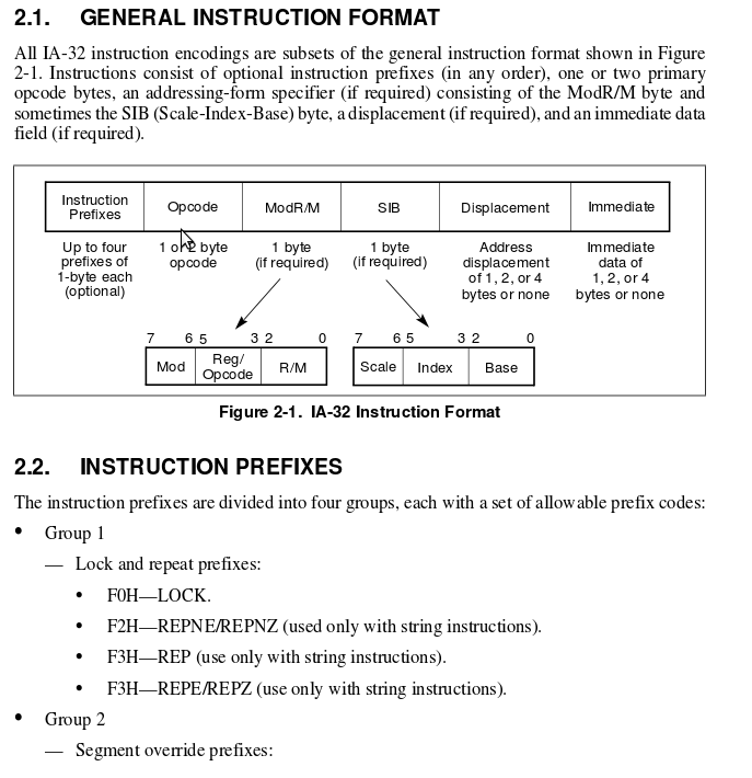 >
>
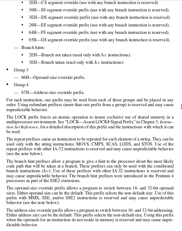
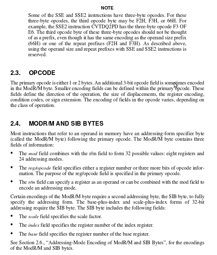
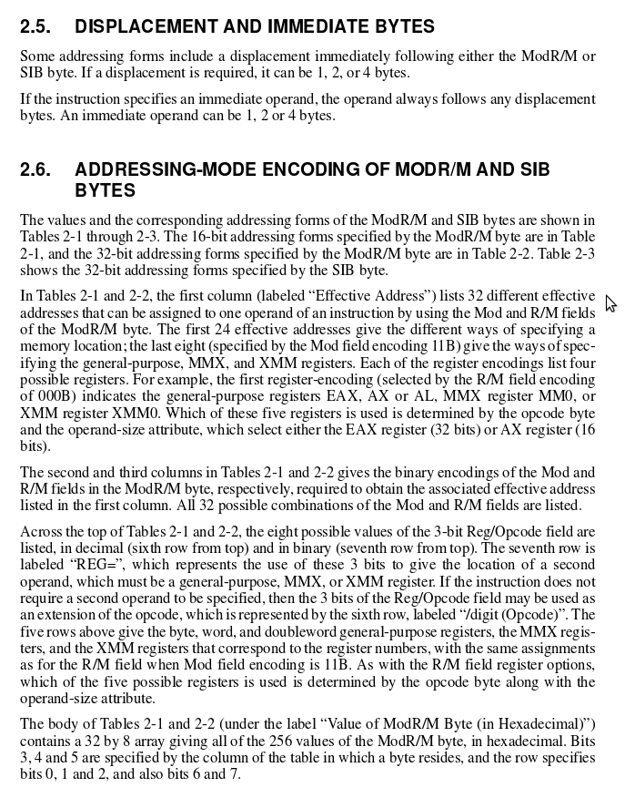
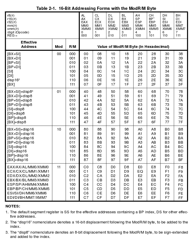
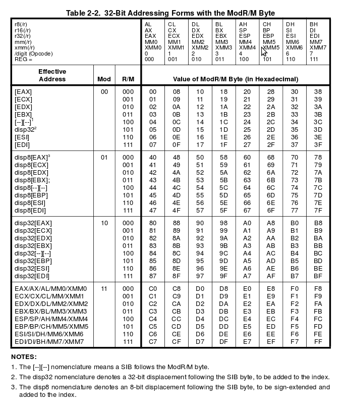
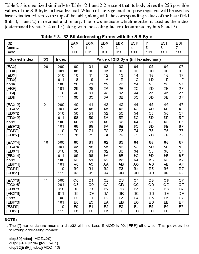 intel64-ia32.pdf full 3439 pages 16.8MB including Instructions(pdf)
The X86-64 and IA-32 are CISC, Complex Instruction Set Computer.
This is in contrast to computer architectures such as the
Alpha, MIPS, PowerPC = Power4 = MAC G5, etc. that are
RISC, Reduced Instruction Set Computer. "Reduced" does not
mean, necessarily, fewer instructions. "Reduced" means
lower complexity and more regularity. Typically all instructions
are the same number of bytes. Four bytes equals 32 bits is the most
popular. Regular in the sense that all registers are general
purpose. Not like the IA-32 using EAX and EDX for multiply
and divide, X86-64 using RAX and RDX for multiply
All MIPS instructions are 32 bits, the 6 bit major opcode
allows 64 instructions and with the 6 bit minor opcode
there may be 4096 instructions. Just a few instruction are shown:
easier to program and simulate
Alpha another RISC architecture
intel64-ia32.pdf full 3439 pages 16.8MB including Instructions(pdf)
The X86-64 and IA-32 are CISC, Complex Instruction Set Computer.
This is in contrast to computer architectures such as the
Alpha, MIPS, PowerPC = Power4 = MAC G5, etc. that are
RISC, Reduced Instruction Set Computer. "Reduced" does not
mean, necessarily, fewer instructions. "Reduced" means
lower complexity and more regularity. Typically all instructions
are the same number of bytes. Four bytes equals 32 bits is the most
popular. Regular in the sense that all registers are general
purpose. Not like the IA-32 using EAX and EDX for multiply
and divide, X86-64 using RAX and RDX for multiply
All MIPS instructions are 32 bits, the 6 bit major opcode
allows 64 instructions and with the 6 bit minor opcode
there may be 4096 instructions. Just a few instruction are shown:
easier to program and simulate
Alpha another RISC architecture
Lecture 26 Data paths
The CPU can be described by control paths and data paths.
We will look at a much simpler architecture than the Intel.
The pipeline for this architecture has stages.
All registers in each stage use the system clk
with exception of writing into a register uses clk_bar.
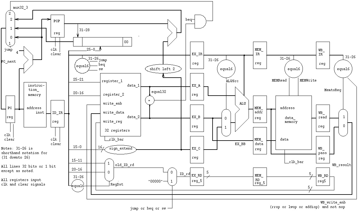 Follow an instruction through the piplined architecture.
a few opcodes
The branch slot, programming to avoid delays (filling in nop's):
Note: beq and jump always execute the next physical instruction.
This is called the "delayed branch slot".
if(a==b) x=3; /* simple C code */
else x=4;
y=5;
lw $1,a # possible unoptimized assembly language
lw $2,b # no ($0) shown on memory access
nop # wait for b to get into register 2
nop # wait for b to get into register 2
beq $1,$2,lab1
nop # branch slot, always executed *********
lwim $1,4 # else part
nop # wait for 4 to get into register 1
nop # wait for 4 to get into register 1
sw $1,x # x=4;
j lab2
nop # branch slot, always executed *********
lab1: lwim $1,3 # true part
nop # wait for 3 to get into register 1
nop # wait for 3 to get into register 1
sw $1,x # x=3;
lab2: lwim $1,5 # after if-else, always execute
nop # wait for 5 to get into register 1
nop # wait for 5 to get into register 1
sw $1,y # y=5;
Unoptimized, 20 instructions.
Now, a smart compiler would produce the optimized code:
lw $1,a # possible unoptimized assembly language
lw $2,b # no ($0) shown on memory access
lwim $4,4 # for else part later
lwim $3,3 # for true part later
beq $1,$2,lab1
lwim $5,5 # branch slot, always executed, for after if-else
j lab2
sw $4,x # x=4; in branch slot, always executed !! after jump
lab1: sw $3,x # x=3;
lab2: sw $5,y # y=5;
Optimized, 10 instructions.
The pipeline stage diagram for a==b true is:
1 2 3 4 5 6 7 8 9 10 11 12 clock
lw $1,a IF ID EX MM WB
lw $2,b IF ID EX MM WB
lwim $4,4 IF ID EX MM WB
lwim $3,3 IF ID EX MM WB
beq $1,$2,L1 IF ID EX MM WB assume equal, branch to L1
lwim $5,5 IF ID EX MM WB delayed branch slot
j L2
sw $4,x
L1:sw $3,x IF ID EX MM WB
L2:sw $5,y IF ID EX MM WB
1 2 3 4 5 6 7 8 9 10 11 12
The pipeline stage diagram for a==b false is:
1 2 3 4 5 6 7 8 9 10 11 12 13 clock
lw $1,a IF ID EX MM WB
lw $2,b IF ID EX MM WB
lwim $4,4 IF ID EX MM WB
lwim $3,3 IF ID EX MM WB
beq $1,$2,L1 IF ID EX MM WB assume not equal
lwim $5,5 IF ID EX MM WB
j L2 IF ID EX MM WB jumps to L2
sw $4,x IF ID EX MM WB
L1:sw $3,x
L2:sw $5,y IF ID EX MM WB
1 2 3 4 5 6 7 8 9 10 11 12 13
if(a==b) x=3; /* simple C code */
else x=4;
y=5;
Renaming when there are extra registers that the programmer can
not access (diagram in Alpha below) with multiple units there can be
multiple issue (parallel execution of instructions)
Out of order execution to avoid delays. As seen in the first example,
changing the order of execution without changing the semantics of the
program can achieve faster execution.
There can be multiple issue when there are multiple arithmetic and
other units. This will require significant hardware to detect the
amount of out of order instructions that can be issued each clock.
Now, hardware can also be pipelined, for example a parallel multiplier.
Suppose we need to have at most 8 gate delays between pipeline
registers.
Follow an instruction through the piplined architecture.
a few opcodes
The branch slot, programming to avoid delays (filling in nop's):
Note: beq and jump always execute the next physical instruction.
This is called the "delayed branch slot".
if(a==b) x=3; /* simple C code */
else x=4;
y=5;
lw $1,a # possible unoptimized assembly language
lw $2,b # no ($0) shown on memory access
nop # wait for b to get into register 2
nop # wait for b to get into register 2
beq $1,$2,lab1
nop # branch slot, always executed *********
lwim $1,4 # else part
nop # wait for 4 to get into register 1
nop # wait for 4 to get into register 1
sw $1,x # x=4;
j lab2
nop # branch slot, always executed *********
lab1: lwim $1,3 # true part
nop # wait for 3 to get into register 1
nop # wait for 3 to get into register 1
sw $1,x # x=3;
lab2: lwim $1,5 # after if-else, always execute
nop # wait for 5 to get into register 1
nop # wait for 5 to get into register 1
sw $1,y # y=5;
Unoptimized, 20 instructions.
Now, a smart compiler would produce the optimized code:
lw $1,a # possible unoptimized assembly language
lw $2,b # no ($0) shown on memory access
lwim $4,4 # for else part later
lwim $3,3 # for true part later
beq $1,$2,lab1
lwim $5,5 # branch slot, always executed, for after if-else
j lab2
sw $4,x # x=4; in branch slot, always executed !! after jump
lab1: sw $3,x # x=3;
lab2: sw $5,y # y=5;
Optimized, 10 instructions.
The pipeline stage diagram for a==b true is:
1 2 3 4 5 6 7 8 9 10 11 12 clock
lw $1,a IF ID EX MM WB
lw $2,b IF ID EX MM WB
lwim $4,4 IF ID EX MM WB
lwim $3,3 IF ID EX MM WB
beq $1,$2,L1 IF ID EX MM WB assume equal, branch to L1
lwim $5,5 IF ID EX MM WB delayed branch slot
j L2
sw $4,x
L1:sw $3,x IF ID EX MM WB
L2:sw $5,y IF ID EX MM WB
1 2 3 4 5 6 7 8 9 10 11 12
The pipeline stage diagram for a==b false is:
1 2 3 4 5 6 7 8 9 10 11 12 13 clock
lw $1,a IF ID EX MM WB
lw $2,b IF ID EX MM WB
lwim $4,4 IF ID EX MM WB
lwim $3,3 IF ID EX MM WB
beq $1,$2,L1 IF ID EX MM WB assume not equal
lwim $5,5 IF ID EX MM WB
j L2 IF ID EX MM WB jumps to L2
sw $4,x IF ID EX MM WB
L1:sw $3,x
L2:sw $5,y IF ID EX MM WB
1 2 3 4 5 6 7 8 9 10 11 12 13
if(a==b) x=3; /* simple C code */
else x=4;
y=5;
Renaming when there are extra registers that the programmer can
not access (diagram in Alpha below) with multiple units there can be
multiple issue (parallel execution of instructions)
Out of order execution to avoid delays. As seen in the first example,
changing the order of execution without changing the semantics of the
program can achieve faster execution.
There can be multiple issue when there are multiple arithmetic and
other units. This will require significant hardware to detect the
amount of out of order instructions that can be issued each clock.
Now, hardware can also be pipelined, for example a parallel multiplier.
Suppose we need to have at most 8 gate delays between pipeline
registers.
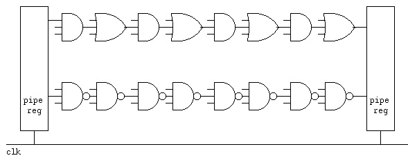 Note that any and-or-not logic can be converted to use only nand gates
or only nor gates. Thus, two level logic can have two gate delays.
We can build each multiplier stage with two gate delays. Thus we can
have only four multiplier stages then a pipeline register. Using a
carry save parallel 32-bit by 32-bit multiplier we need 32 stages, and
thus eight pipeline stages plus one extra stage for the final adder.
Note that any and-or-not logic can be converted to use only nand gates
or only nor gates. Thus, two level logic can have two gate delays.
We can build each multiplier stage with two gate delays. Thus we can
have only four multiplier stages then a pipeline register. Using a
carry save parallel 32-bit by 32-bit multiplier we need 32 stages, and
thus eight pipeline stages plus one extra stage for the final adder.
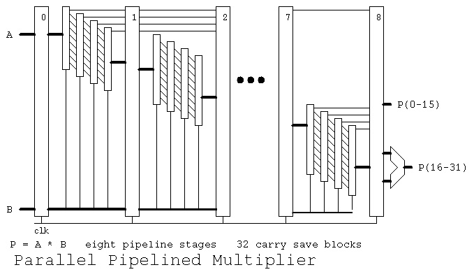 Note that a multiply can be started every clock. Thus a multiply
can be finished every clock. The speedup including the last adder
stage is 9 as shown in:
pipemul_test.vhdl
pipemul_test.out
pipemul.vhdl
A 64-bit PG adder may be built with eight or less gate delays.
The signals a, b and sum are 64 bits. See add64.vhdl for details.
Note that a multiply can be started every clock. Thus a multiply
can be finished every clock. The speedup including the last adder
stage is 9 as shown in:
pipemul_test.vhdl
pipemul_test.out
pipemul.vhdl
A 64-bit PG adder may be built with eight or less gate delays.
The signals a, b and sum are 64 bits. See add64.vhdl for details.
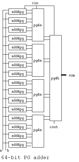 add64.vhdl
Any combinational logic can be performed in two levels with "and" gates
feeding "or" gates, assuming complementation time can be ignored.
Some designers may use diagrams but I wrote a Quine McClusky minimization
program that computes the two level and-or-not VHDL statement
for combinational logic.
quine_mcclusky.c logic minimization
eqn4.dat input data
eqn4.out both VHDL and Verilog output
there are 2^2^N possible functions of N bits
Not as practical, I wrote a Myhill minimization of a finite state machine,
a Deterministic Finite Automata, that inputs a state transition table
and outputs the minimum state equivalent machine. "Not as practical"
because the design of sequential logic should be understandable. The
minimized machine's function is typically unrecognizable.
myhill.cpp state minimization
initial.dfa input data
myhill.dfa minimized output
A reasonably complete architecture description for the Alpha
showing the pipeline is:
basic Alpha
more complete Alpha
The "Cell" chip has unique architecture:
IBM cell architecure
Cell architecture
Some technical data on Intel Core Duo (With some advertising.)
Core Duo all on WEB
From Intel, with lots of advertising:
power is proportional to capacitance * voltage^2 * frequency, page 7.
tech overview
whitepaper
Intel quad core demonstrated
AMD quad core
By 2010 AMD had a 12-core available and Intel had a 8-core available.
and 24 core and 48 core AMD
IBM Power6 at 4.7GHz clock speed
Intel I7 920 Nehalem 2.66GHz not quad $279.99
Intel I7 940 Nehalem 2.93GHz quad core $569.99
Intel I7 965 Nehalem 3.20GHz quad core $999.99
Prices vary with time, NewEgg.com search Intel I7
add64.vhdl
Any combinational logic can be performed in two levels with "and" gates
feeding "or" gates, assuming complementation time can be ignored.
Some designers may use diagrams but I wrote a Quine McClusky minimization
program that computes the two level and-or-not VHDL statement
for combinational logic.
quine_mcclusky.c logic minimization
eqn4.dat input data
eqn4.out both VHDL and Verilog output
there are 2^2^N possible functions of N bits
Not as practical, I wrote a Myhill minimization of a finite state machine,
a Deterministic Finite Automata, that inputs a state transition table
and outputs the minimum state equivalent machine. "Not as practical"
because the design of sequential logic should be understandable. The
minimized machine's function is typically unrecognizable.
myhill.cpp state minimization
initial.dfa input data
myhill.dfa minimized output
A reasonably complete architecture description for the Alpha
showing the pipeline is:
basic Alpha
more complete Alpha
The "Cell" chip has unique architecture:
IBM cell architecure
Cell architecture
Some technical data on Intel Core Duo (With some advertising.)
Core Duo all on WEB
From Intel, with lots of advertising:
power is proportional to capacitance * voltage^2 * frequency, page 7.
tech overview
whitepaper
Intel quad core demonstrated
AMD quad core
By 2010 AMD had a 12-core available and Intel had a 8-core available.
and 24 core and 48 core AMD
IBM Power6 at 4.7GHz clock speed
Intel I7 920 Nehalem 2.66GHz not quad $279.99
Intel I7 940 Nehalem 2.93GHz quad core $569.99
Intel I7 965 Nehalem 3.20GHz quad core $999.99
Prices vary with time, NewEgg.com search Intel I7
Lecture 27 Arithmetic Logic Unit
Often called ALU a major part of the CPU
Quick review:
Basic digital logic
The Arithmetic Logic Unit is the section of the CPU that actually
performs add, subtract, multiply, divide, and, or, floating point and
other operations. The choice of which operations are implemented is
determined by the Instruction Set Architecture, ISA. Most modern
computers separate the integer unit from the floating point unit.
Many modern architectures have simple integer, complex integer, and
an assortment of floating point units.
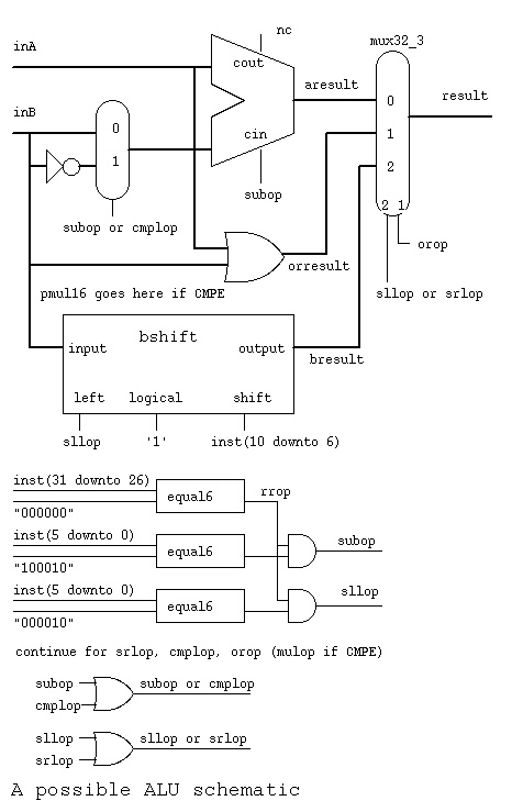 The ALU gets inputs from registers part1.jpg
Where did numbers such as 100010 for subop and 000010 for sllop
come from ? cs411_opcodes.txt
The ALU gets inputs from registers part1.jpg
Where did numbers such as 100010 for subop and 000010 for sllop
come from ? cs411_opcodes.txt
 Note that bshift.vhdl contains two different architectures
for the same entity. A behavioral architecture using sequential
programming and a circuits architecture using digital logic
components.
bshift.vhdl
An 8-bit version of shift right logical, using single bit signals,
three bit shift count, is:
Note that bshift.vhdl contains two different architectures
for the same entity. A behavioral architecture using sequential
programming and a circuits architecture using digital logic
components.
bshift.vhdl
An 8-bit version of shift right logical, using single bit signals,
three bit shift count, is:
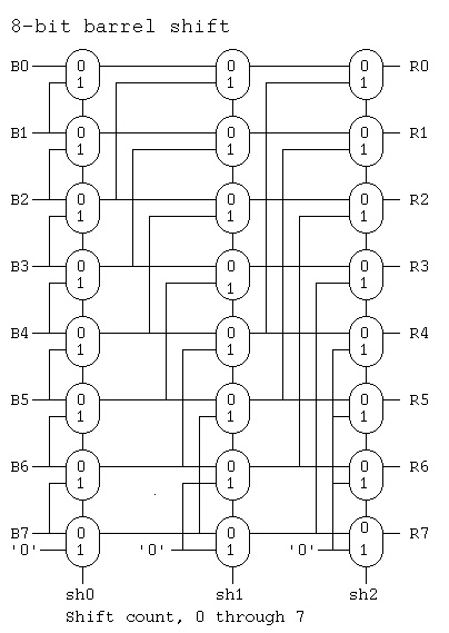 Where diagram said "pmul16 goes here" a parallel multiplier and
a parallel divider would be included. The "result" mux would
get two more data inputs, and two more control inputs:
mulop and divop. Then the upper half of the product and
the remainder would be saved in a temporary register,
the "hi" of the "hi" and "lo" registers shown previously.
Then stored on the next clock cycle in this architecture.
Fully parallel multiplier (possibly pipelined in another architecture)
Where diagram said "pmul16 goes here" a parallel multiplier and
a parallel divider would be included. The "result" mux would
get two more data inputs, and two more control inputs:
mulop and divop. Then the upper half of the product and
the remainder would be saved in a temporary register,
the "hi" of the "hi" and "lo" registers shown previously.
Then stored on the next clock cycle in this architecture.
Fully parallel multiplier (possibly pipelined in another architecture)
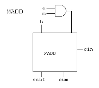 Fully parallel divider (possibly pipelined in another architecture)
There are many ways to build an ALU. Often the choice is based
on mask making and requires a repeated pattern. The "bit slice"
method uses the same structure for every bit. One example is:
Fully parallel divider (possibly pipelined in another architecture)
There are many ways to build an ALU. Often the choice is based
on mask making and requires a repeated pattern. The "bit slice"
method uses the same structure for every bit. One example is:
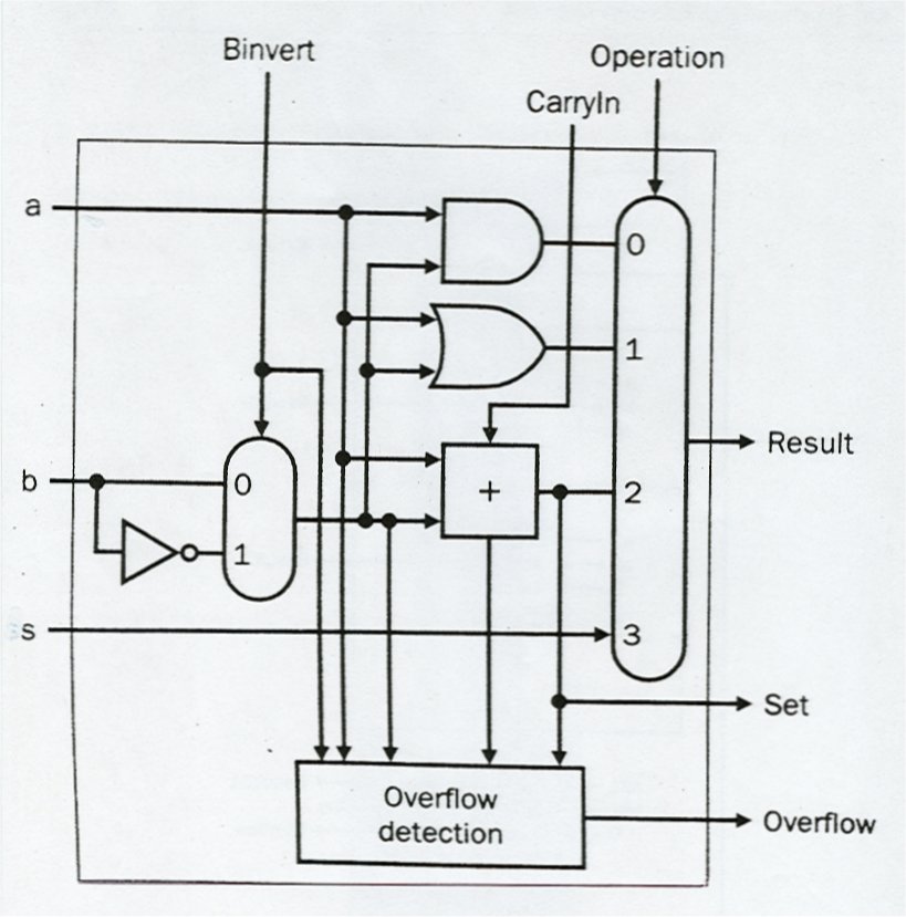 Note that 'Operation' is two bits, 0 for logical and, 1 for logical or,
2 for add or subtract, and 3 for an operation called set used for
comparison.
'Binvert' and 'CarryIn' would be set to '1' for subtract.
'Binvert' and 'a' set to '0' would be complement.
The overflow detection is in every stage yet only used in the
last stage.
The bit slices are wired together to form a simple ALU:
Note that 'Operation' is two bits, 0 for logical and, 1 for logical or,
2 for add or subtract, and 3 for an operation called set used for
comparison.
'Binvert' and 'CarryIn' would be set to '1' for subtract.
'Binvert' and 'a' set to '0' would be complement.
The overflow detection is in every stage yet only used in the
last stage.
The bit slices are wired together to form a simple ALU:
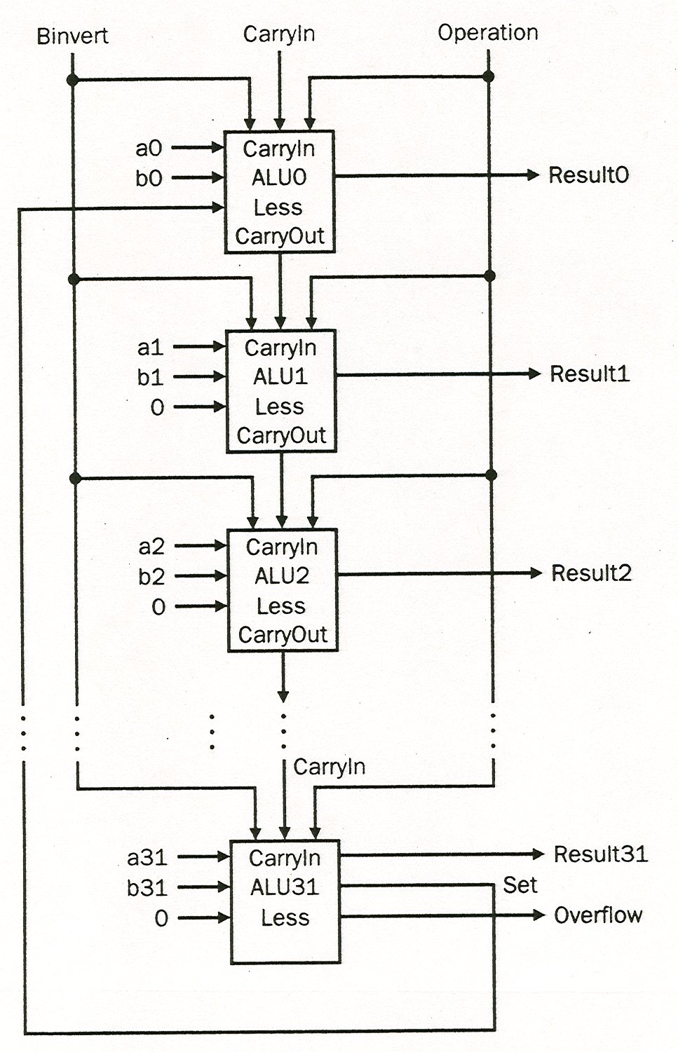 The 'set' operation would give non zero if 'a' < 'b' and
zero otherwise. A possible condition status or register
value for a "beq" instruction.
If overflow was to be detected, the circuit below uses the
sign bit of the A and B inputs and the sign bit of the
result to detect overflow on twos complement addition.
The 'set' operation would give non zero if 'a' < 'b' and
zero otherwise. A possible condition status or register
value for a "beq" instruction.
If overflow was to be detected, the circuit below uses the
sign bit of the A and B inputs and the sign bit of the
result to detect overflow on twos complement addition.
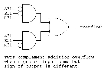 Time to submit any outstanding projects
Lecture 28 Architecture
32-bit and 64-bit ALU architectures are available.
A 64-bit architecture, by definition, has 64-bit integer registers.
Many computers have had 64-bit IEEE floating point for many years.
The 64-bit machines have been around for a while as the Alpha and
PowerPC yet have become popular for the desktop with the Intel and
AMD 64-bit machines.
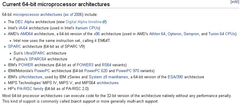 Software has been dragging well behind computer architecture.
The chaos started in 1979 with the following "choices."
Software has been dragging well behind computer architecture.
The chaos started in 1979 with the following "choices."
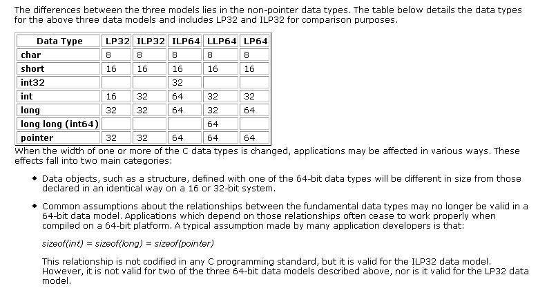 The full whitepaper www.unix.org/whitepapers/64bit.html
My desire is to have the compiler, linker and operating system be ILP64.
All my code would work fine. I make no assumptions about word length.
I use sizeof(int) sizeof(size_t) etc. when absolutely needed.
On my 8GB computer I use a single array of over 4GB thus the subscripts
must be 64-bit. The only option, I know of, for gcc is -m64 and that
just gives LP64. Yuk! I have to change my source code and use "long"
everywhere in place of "int". If you get the idea that I am angry with
the compiler vendors, you are correct!
The early 64-bit computers were:
DEC Alpha
DEC Alpha
IBM PowerPC
Some history of 64-bit computers:
The full whitepaper www.unix.org/whitepapers/64bit.html
My desire is to have the compiler, linker and operating system be ILP64.
All my code would work fine. I make no assumptions about word length.
I use sizeof(int) sizeof(size_t) etc. when absolutely needed.
On my 8GB computer I use a single array of over 4GB thus the subscripts
must be 64-bit. The only option, I know of, for gcc is -m64 and that
just gives LP64. Yuk! I have to change my source code and use "long"
everywhere in place of "int". If you get the idea that I am angry with
the compiler vendors, you are correct!
The early 64-bit computers were:
DEC Alpha
DEC Alpha
IBM PowerPC
Some history of 64-bit computers:
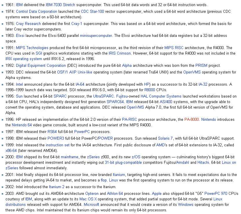 Java for 64-bit, source compatible
Don't panic, you do not need to understand everything about
the Intel Itanium architecture:
IA-64 Itanium
Some history of the evolution of Intel computers:
Intel X86 development
long list
now quantum
Java for 64-bit, source compatible
Don't panic, you do not need to understand everything about
the Intel Itanium architecture:
IA-64 Itanium
Some history of the evolution of Intel computers:
Intel X86 development
long list
now quantum
Lecture 29 Review
  Review previous lectures

  Sample questions will be presented in class.
Lecture 30 Final Exam
The midterm was considered the end of the Assembly Language
part of this course. Thus, the final exam will cover
lectures 15 through 29 on digital logic and computer organization.

There will be questions of types:
  true-false
  multiple choice
  short answer (words, numbers, logic equations)

     know the symbols and truth tables for
     "and"  "nand" "or"  "nor" "not"  "xor" "mux"  "dff"

     know how to recognize the corresponding State Diagram,
     State Transition Table and schematic and VHDL statements
     for sequential logic. (e.g. project)

     know how to construct Karnaugh map from minterms.

     know how to get VHDL equation from Karnaugh map.

     recognize adders, subtractors and simple logic circuits.

     understand data flow through a computer architecture.

Automate!
Other links
Go to top
Last updated 11/3/2014